![]()
Cost Savings Through VFD Integration in a Drinking Water Distribution System
Intended Audience: Water Distribution
Objective: Replace the constant speed motors with VFD driven motors to match the varying flow rate demand of the water distribution system.
Description of System: A drinking water distribution system serving a small residential community—operating without a hydro-pneumatic tank—draws water from a reservoir using two booster pumps (one duty, one standby). Each pump is powered by a 22-kW (30 hp) constant-speed, standard-efficiency induction motor controlled via an across-the-line starter. The system is designed to maintain a consistent pressure of 550 kPa (80 psi) using a hydraulically controlled bypass relief valve, which discharges excess water back to the suction reservoir. Each pump is rated for 90 m³/h (400 gpm) at 550 kPa (80 psi) and 75% pump efficiency. The system is graphically represented below:
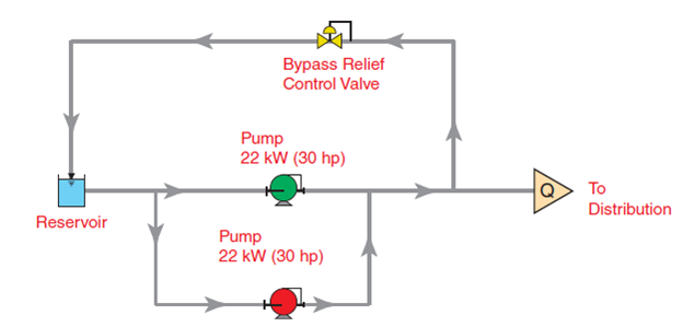
Figure 1: Schematic with constant speed drive and bypass relief valve
The following diurnal flow rate demand curve illustrates the average hourly demand over a typical 24-hour period. Over the course of a typical 24-hour day, the flow rate varies from 19 m³/h (85 gpm) to 90 m³/h (400 gpm). The shaded region above the curve but below the 90 m³/h (400 gpm) curve represents the flow rate being recirculated through the bypass relief valve.
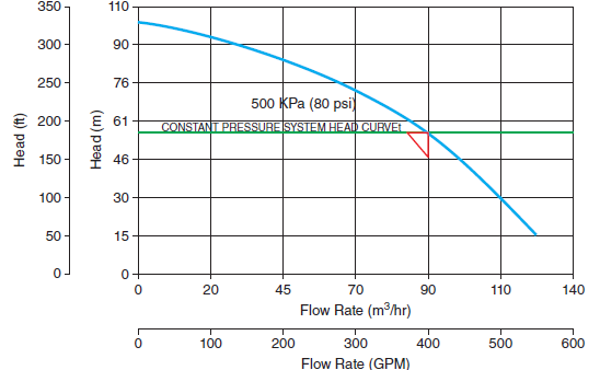
Figure 2: Constant speed system and pump performance curve
The following diurnal flow rate demand curve illustrates the average hourly demand over a typical 24-hour period. Over the course of a typical 24-hour day, the flow rate varies from 19 m³/h (85 gpm) to 90 m³/h (400 gpm). The shaded region above the curve but below the 90 m³/h (400 gpm) curve represents the flow rate being recirculated through the bypass relief valve.
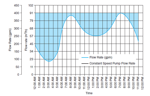
Figure 3: Diurnal flow rate demand curve
Under the existing configuration, the system consumes approximately 483 kWh per day, totaling 176,295 kWh annually. At an energy rate of $0.10/kWh, the yearly operating cost is $17,643, with an additional $750 in routine maintenance.
Description of Intervention: The system was upgraded with Variable Frequency Drives driving premium efficiency induction motors of the same size, at a capital cost of $30,000. The bypass valve and associated recirculation piping were removed and replaced with a pressure transmitter installed on the pump discharge manifold. This transmitter enables dynamic speed control of the pump, maintaining the target pressure of 80 psi while adjusting flow rate in response to real-time demand.
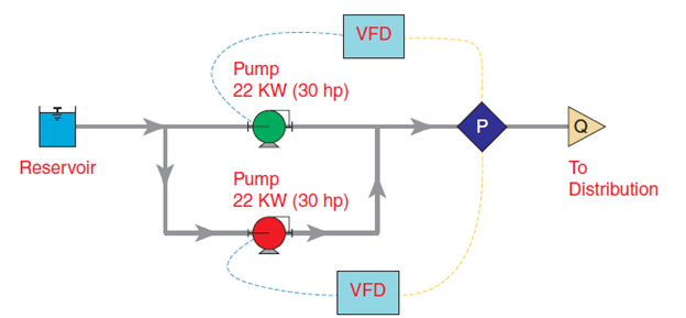
Figure 4: Schematic with VFD
The power draw of the pump during periods of non-peak demand is reduced in accordance with the flow rate demand, saving energy throughout the day. The difference between constant speed power and the power draw of a variable speed option is illustrated below.
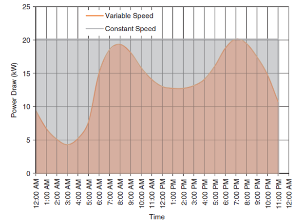
Figure 5: Power consumption curve
By modulating motor speed during periods of reduced demand, the system significantly lowers energy consumption. Post-upgrade, daily energy usage dropped to 323 kWh, resulting in an annual consumption of 117,895 kWh and a reduced energy cost of $11,779—a savings of $5,864 per year. Importantly, operation and maintenance costs remain unchanged.
Summary of Results: An LCC analysis is performed to compare costs between the original and new systems. A summary is provided in Table 1:
Table 1 LCC analysis
| LCC Elements | Original | New |
| Initial Investment | N/A | $30,000 |
| Annual Energy Cost | $17,643 | $11,779 |
| Annual O&M Cost | $750 | $750 |
| Total Annual Cost | $18,393 | $12,529 |
| Annual Savings | N/A | $5,864 |
| Total lifetime cost at present value | $204,501 | $169,302 |
Over the course of the project life, the new system saves $35,200. The payback summary is reported below in Table 2.
Table 2: Simple payback summary of new system
| Annual energy cost before installation | $17,643 |
| Annual energy cost after installation | $11,779 |
| Annual energy cost savings | $5,864 |
| Project capital cost | $30,000 |
| Project Life | 15 Years |
| Discount Rate | 4 % |
| Net present value | $35,200 |
| Simple payback | 5.1 Years |
| IRR | 17.9 % |
Conclusion: This retrofit demonstrates how transitioning from constant-speed motors with bypass control to VFD-driven systems can yield substantial energy and cost savings, while enhancing operational responsiveness and sustainability in municipal water infrastructure. VFDs can also alternate pump operation to prevent backup pump seizure and ensure even wear across both units.
Written by: Members of the Committee, 1st Edition
Published In: Pump Systems Optimization: A Guide for Improved Energy Efficiency, Reliability, and Profitability
Year of Publication: 2018