![]()
Pump FAQs
This collection of frequently asked questions is categorized into four categories for your convenience.
Rotodynamic Pumps / Positive Displacement Pumps / Pump Systems / General Pump Standards
Rotodynamic Pumps
-
What items need to be included in regular pump maintenance, and what schedule should be followed?
Pumping systems can be complex, with many moving parts and subsystems that need to be regularly inspected and constantly maintained. Failure to frequently inspect pumping systems can lead to premature failure, losses in efficiency and increased operating costs. Therefore, it is recommended that a monitoring, maintenance and schedule be adopted, and it should include, at a minimum, the following:
- When applicable, gland packings must be adjusted to maintain concentric alignment of the gland follower and maintain specified leakage so that the packing and follower do not overheat.
- Check for any leaks from gaskets and seals. The correct functioning of the shaft seal must be checked regularly.
- Check bearing lubricant level and verify if the hours run show a lubricant change is required.
- Check and verify that the duty condition is in the allowable operating region for the pump.
- Check vibration, noise level and surface temperature at the bearings to confirm satisfactory operation.
- Check that dirt and dust are removed from areas around close clearances, bearing housings and motors.
- Check coupling alignment and realign if necessary.
Note: Additionally, installed auxiliary systems should be included in the maintenance plan so they are monitored and maintained to ensure they function properly.
An inspection and maintenance log should be kept and problems that are identified should be reported immediately. A suggested guide for preventative maintenance for normal applications is given below. Unusual applications with abnormal heat, moisture, dust, etc., may require more frequent inspection and service.
A maintenance plan should include required spare parts to keep on hand. A list of recommended spare parts will depend on normal supplier lead time when ordering parts; whether pumping equipment is used for “normal duty” or “severe duty;” and whether or not there is backup pumping while a unit is down for maintenance. Below is a suggested list of spare parts for pumping units. Note that the items listed for severe duty are in addition to the items listed for normal duty.
For more information about how to maintain pumping systems, refer to ANSI/HI 14.4 Rotodynamic Pumps for Installation, Operation, and Maintenance


May 2018
-
How does a centrifugal pump work?
A centrifugal pump is a type of rotodynamic pump that uses bladed impellers with essentially radial outlet to transfer rotational mechanical energy to the fluid primarily by increasing the fluid kinetic energy (angular momentum) and increasing potential energy (static pressure). Kinetic energy is then converted into usable pressure energy in the discharge collector.
Figure 1 provides a cross section view of a centrifugal pump, which shows the use of a rotating impeller to add energy to the pumped liquid. The liquid enters the impeller axially at a smaller diameter, called the impeller eye, and progresses radially between the vanes until it exits at the outside diameter. As the liquid leaves the impeller, it is collected in a pressure container casing. One design referred to as a volute collects the flow and efficiently directs it to a discharge nozzle.

Figure 2 highlights the discharge nozzle, which is shaped like a cone so that the high-velocity flow from the impeller is gradually reduced. This cone-shaped discharge nozzle is also called a diffuser. During the reduction in velocity in the diffuser, energy in the flow is converted to pressure energy. An optimum angle of seven to 10 degrees is used to most efficiently convert velocity energy to pressure energy.
Centrifugal pumps can have many drivers, but the most common is the electric motor. The motor provides the mechanical energy to pump shaft through a coupling. The radial and axial loads are carried by pump and/or motor bearings. Sealing of the pumped fluid can be done with compression packing or mechanical seals. Additionally, sealless designs are available with canned motors or magnetic drive couplings.
For more information on centrifugal pumps, their construction and typical industries served, refer to HI’s Rotodynamic Pump Certificate training modules.
May 2018
- What are the applications of vertical turbine pumps?
-
What is a chopper pump?
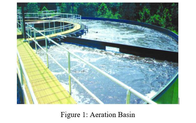
Chopper pumps are centrifugal pumps with the capability to handle fluids with a high concentration of solids. Chopper pumps have a cutting attachment added made of hard materials of fixed and rotating elements that macerate solids before entry to the impeller that allows it to handle difficult materials. They cut solids so they pass through the pump more easily and flow out with the rest of the pumped fluid.
A chopper pump’s ability to handle solids gives them more flexibility in what they can pump; this characteristic makes them particularly useful in wastewater treatment plants. Wastewater treatment is split into primary treatment and secondary treatment. Primary treatment is the physical separation of float-able materials and insoluble solids from the wastewater. Secondary treatment is biological treatment of water using microorganisms to remove the remaining solids in the fluid. Both treatments contain solids in the pumped fluid and may require chopper pumps.
Specific steps in the process include pumping scum, mixing the contents of the aeration basin and the anoxic zone, and pumping sludge. Image 1 shows an example of an aeration basin at a treatment facility where chopper pumps mix oxygen with wastewater to encourage the growth of microorganisms to break down solids.
A typical centrifugal pump impeller is more easily clogged by solids, which can halt pumping and cause damage to the system. In particular, stringy materials found in wastewater during the treatment process is especially troublesome to normal centrifugal pumps as the material can tangle the impeller. However, the chopper pump is more effective in dealing with this issue.
For more information on the application of pumps in power plants, refer to HI Guideline Wastewater Treatment Plant Pumps.
September 2018
-
I am used to hearing the term “centrifugal” pump, but sometimes hear them referred to as “rotodynamic” pumps. Are centrifugal and rotodynamic terms that can be used synonymously?
Rotodynamic pumps are kinetic machines in which energy is continuously imparted to the pumped fluid by means of a rotating impeller, propeller or rotor. These pumps transfer mechanical energy to the fluid primarily by increasing the fluid kinetic energy. Kinetic energy is then converted into potential energy (pressure) in the discharge collector. The most common types of rotodynamic pumps are radial (centrifugal), mixed flow and axial flow (propeller) pumps, including pumps historically referred to as vertical turbine pumps. Radial, mixed and axial flow impellers are shown in Image 1.
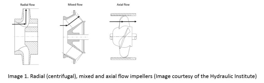
As seen from the definition of a rotodynamic pump and Image 1, it is a term used to describe a larger group of pumps that includes centrifugal (radial flow) pumps, but also includes pumps of mixed and axial flow pumps and some other unique constructions. Centrifugal pumps are the most common type and the term is synonymous with radial flow impellers where the flow enters the impeller in line with the pump shaft but discharges the impeller perpendicular to the pump shaft.
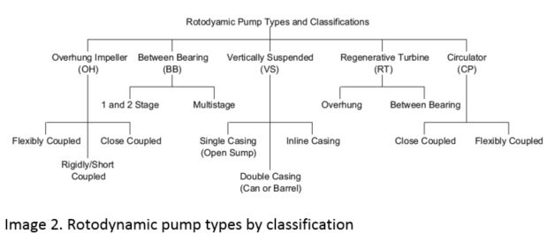
Rotodynamic pump types are also commonly described by their general mechanical configuration as described in Image 2.
So, to answer the question directly, a centrifugal pump is a type rotodynamic pump, and not all rotodynamic pumps are centrifugal pumps.
For more information on rotodynamic pumps refer to ANSI/HI 14.1-14.2 rotodynamic pumps for nomenclature and definitions, and ANSI/HI 14.3 rotodynamic pumps for design and application.
February 2019
-
What are the benefits of multistage pumps?
Multistage pumps use multiple impellers plus diffusing element stages for developing higher head through the series addition of head from one stage to the next. Types of multistage pumps include the between bearing types, which consist of the axially split BB3 and the radially split BB4 and BB5. These pumps are typically used in applications for boiler feed, reverse osmosis, and other high pressure and temperature applications. Overhung impeller multistage pumps such as the OH7j, the OH1j and the OH13j are useful in low-flow, high-pressure applications and control hydraulic radial load through the use of diffusers.
For multistage pumps, a low NPSH required (NPSHr) first stage can be added to supply the second stage. This is especially applicable when the second stage has a higher NPSHr than the first stage. Vertical and horizontal multistage pumps behave similarly to multiple single-stage pumps operating in series. This should be considered when designing a pumping system that has higher head requirements.
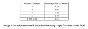
Multistage pumps may also be useful for noise reduction. For pumps of the same power, an increase in the number of stages lowers noise levels compared to a single stage. Estimates for sound pressure reductions for increased stages at the same power level can be referenced in Image 2.
For more information about valves and multistage pumping, refer to ANSI/HI 14.1-14.2 Rotodynamic Pumps for Nomenclature and Definitions and ANSI/HI 14.3 Rotodynamic Pumps for Design & Applications
September 2019
- What are essential spare parts to keep on hand for rotodynamic pumps?
Positive Displacement Pumps
-
What are some differences between simplex and duplex air-operated pumps?
For a duplex air-operated pump, compressed air is directed into the pump air chamber via the air distribution system. The compressed air is separated from the liquid by a diaphragm. The diaphragm, in turn, applies pressure on the liquid and forces it out of the pump discharge. While this is occurring, the opposite-side air chamber is depressurized and exhausted to atmosphere and liquid is drawn into the pump suction. The cycle repeats, thus creating a constant reciprocating action, which maintains flow through the pump. (See Figure 10.4.2.1).
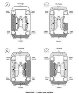
A simplex pump operates in much the same manner except that no liquid is discharged during the recharge stroke of the diaphragm or bellows. A spring return is typically used to return the diaphragm and provide energy for the suction stroke. Intake and discharge valves direct flow into and out of the pumping chamber. It should also be noted that simplex pumps require a controller to cycle the compressed air/gas into the air chamber of the pump and to exhaust the air out. The controller can be mechanical or electrical, such as a repeat cycle timer and solenoid valve. The speed of the pump is set by the controller, and the maximum speed is determined by the manufacturer.
To determine the maximum pumping speed on a duplex pump, increase the air supply while the pump rate of flow increases. When the rate of flow no longer increases, throttle back the air supply until the pump rate of flow starts to decrease. This point is the optimum pump cycle rate achievable under these system conditions.
For more information about air-operated pumps see ANSI/HI 10.1-10.5 Air-Operated Pumps for Nomenclature, Definitions, Application, and Operation.
December 2014
- How strong of a foundation do reciprocating pumps typically need?
- What is a relief valve and are all pumps required to be equipped with one?
-
How can I ensure I have enough torque to start a Positive Displacement (PD) Pump?
There are two main concerns regarding the torque required to start a PD pump. First, PD pumps deliver an almost constant volume of fluid with each shaft revolution that is relatively independent of pressure; therefore, they can produce maximum pressure and require maximum torque at startup which is a key difference compared to centrifugal pumps. The driver selection needs to consider this and be selected accordingly.
The National Electrical Manufacturers Association (NEMA) has assigned a simple letter designation to four of the most common three-phase AC induction motors. These vary in starting torque and speed regulation. They are all squirrel-cage construction, and are available in many sizes. Image 1 shows the motor torque as a function of percent speed for each NEMA design designation.
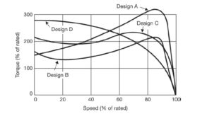
Image 1 – NEMA motor design torque with respect to speed
NEMA Design A
Design A has normal starting torque (typically 150–170% of rated) and relatively high starting current. Breakdown torque is the highest of all NEMA types.
NEMA Design B
Design B is currently the most common type of AC induction motor sold and used with pumps. It has normal starting torque, similar to Design A, but offers low starting current. Locked rotor torque sufficient to start many loads encountered in industrial applications.
NEMA Design C
Design C has higher starting torque (greater than the previous two designs, e.g., 200%), useful for driving heavy breakaway loads. These motors are intended for operation near full speed without great overloads.
NEMA Design D
Design D has the highest locked rotor, but has high slip values (5-13%) which make this motor suitable for applications with changing loads and sharp changes in motor speed, such as in machinery with flywheel energy storage. However, speed regulation is poor. They are typically used for punch presses, cranes, elevators, and oil well pumps. This motor type is usually considered a special-order item.
For more Information regarding Motor selection refer to Drivers Application Guidebook: Electric Motors available for purchase.
September 2020
- How can I determine the pump input power for a reciprocating pump?
-
What are the design features of untimed rotary screw pumps and in what applications can they be used?
Screw pumps are used in oil field, pipeline, refinery, marine, power generation, chemical, hydraulic systems, and general industrial applications for transfer, lubrication, injection, and hydraulics handling a wide range of fluids, such as fuel oils, lube oils and greases, asphalts, noncorrosive viscous chemicals, and high-pressure coolants.
The untimed rotary screw pump is an axial-flow, multirotor, positive displacement design used in a wide range of applications in pumping clean to mildly abrasive viscous liquids. The design may use two, three, four, or five screws. The most common configuration is the three-screw pump, which consists of a power rotor (drive screw) and two symmetrically opposed idler rotors (driven screws) that mesh within a close-fitting housing forming a succession of cavities to continuously convey fluid to the pump discharge.
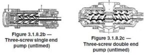
Untimed screw pumps are available with a double-ended flow path as illustrated in Figure 3.1.8.2c or with a single-ended flow path as shown in Figure 3.1.8.2b. Timing is accomplished through rotor geometry. In a properly applied three-screw pump, there is no rotor contact because screws are supported radially in their bores and are hydraulically balanced or free to float on a hydrodynamic film created by the pumped liquid. In other untimed screw pump configurations, the screws may be supported in product-lubricated bushings.
Units are commercially available in product families with flows to 1200 m^3/h (5300 gpm) and discharge pressures to 310 bar (4500 psi). Applications cover a wide viscosity range from 2 to 220,000 cSt (33 to 1,000,000 SSU) and temperatures from below zero to 274°C (500°F). Because of the axial movement of the fluid and the compact diameter of the rotors, untimed screw pumps typically operate at motor speeds (two-, four-, and six-pole). Screw pumps operate with a minimum of noise, vibration, and fluid pulsation. Other characteristics important in many applications are their good suction capability and low shear rate. Untimed screw pumps are frequently found in installations where extended uninterrupted service life is required.
For more information about rotary pumps, see ANSI/HI 3.1-3.5 Rotary Pumps for Nomenclature, Definitions, Application and Operation.
July 2024
-
Is it possible for air operated pumps to be submerged during operation?
Some air-operated pumps are designed to be submerged. Before submerging a pump, check the chemical compatibility of the material of the wetted and nonwetted parts of the pump with the liquid in which the pump is to be submerged. Check the manufacturer’s operation manual for a particular pump before trying to use it in a submergible application.
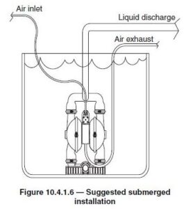
When submerging a pump, a hose should be attached to the pump air exhaust with the exhaust piped above the liquid level to prevent the liquid from entering the pump (see Figure 10.4.1.6). To learn more about air operated pumps, see ANSI/HI 10.1-10.5 Air Operated Pumps for Nomenclature, Definitions, Application, and Operation.
July 2024
- What is the proper method for configuring pressure-measuring instruments during a rotary pump test?
-
In what ways are mechanically coupled and hydraulic coupled disk diaphragm pumps different from one another?
A mechanically coupled disc diaphragm liquid end (see Figure 7.1.2.3) contains a flexible, round diaphragm, clamped at the periphery, which is in direct contact with the process liquid being displaced. This type of design is inherently leak free.
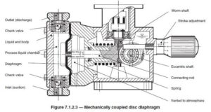
The diaphragm material is typically a fluoropolymer, elastomer, or fluoropolymer-elastomer composite. A connecting rod is connected directly to the diaphragm. The diaphragm is not pressure balanced as the process pressure is acting on one side of the diaphragm and atmospheric pressure is acting on the other side. This results in higher stress levels in the diaphragm and therefore these pumps are typically used for lower pressure applications. In operation, the process liquid is admitted through the suction check valve as the diaphragm/connecting rod assembly moves away from the wet end. As the diaphragm/connecting rod assembly moves towards the wet end, the suction check valve closes and the discharge check valve opens discharging liquid. A hydraulic coupled disc diaphragm liquid end (Figure 7.1.2.4a) contains a flexible, single or double configuration diaphragm, clamped at the periphery, and is in direct contact with the process liquid being displaced. This type of liquid end design is inherently leak free. The diaphragm material is typically a fluoropolymer, elastomer, or fluoropolymer-elastomer composite. Liquid end designs featuring flexible metallic diaphragms are available and used in applications where severe operating conditions prohibit the use of fluoropolymer or other elastomers.
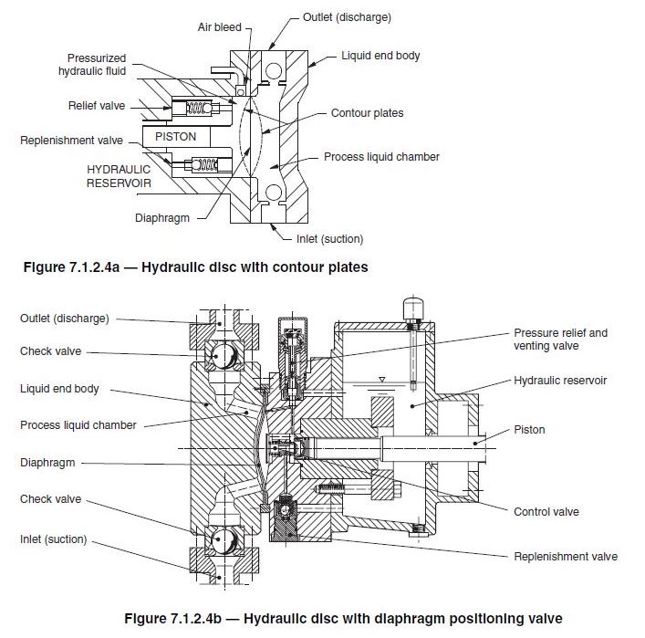
In operation, the diaphragm is moved by a hydraulic fluid, which is displaced by a reciprocating plunger or piston. The stresses in the diaphragm are minimal, as the process pressure acting on one side of the diaphragm is balanced by the hydraulic pressure acting on the opposite side. The process liquid is admitted through the suction check valves as the diaphragm moves rearward. As the diaphragm moves towards the wet end, the suction check valve closes, and the discharge check valve opens discharging liquid. Liquid end designs of this type may include provisions such as contour plates, springs, or diaphragm positioning hydraulic control valves (Figure 7.1.2.4b) to ensure the diaphragm does not move beyond its elastic limits. For additional information regarding various controlled-volume metering pumps, see ANSI/HI 7.1-7.5 Controlled-Volume Metering Pumps for Nomenclature, Definitions, Application, and Operation.
July 2024
-
What principles drive the pumping action in a controlled-volume metering pump?
The pumping action in a controlled-volume metering pump is developed by a reciprocating piston. This reciprocating motion develops a flow profile represented by a sine wave. Actual rate of flow is determined by the following formula:
Rate of flow = Displacement x Cycles per unit of time x Volumetric efficiency
Figure 7.3.1a illustrates how the rate of flow from a reciprocating, controlled-volume metering pump is minimally affected by changes in discharge pressure.
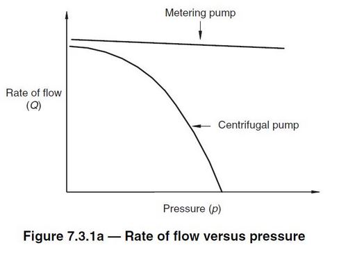
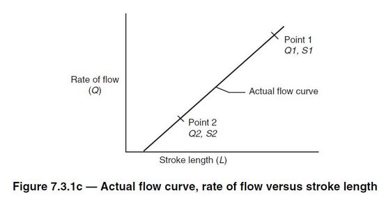
Figure 7.3.1c shows rate of flow versus stroke-length setting for a controlled-volume metering pump at a given pressure and stroking speed. The curve is linear. The curve is not necessarily proportional in that 50% stroke setting may not equal 50% flow. This is because the curve may not pass through zero on both axes simultaneously. By measuring flow at two rate-of-flow settings, plotting both points, and drawing a straight line through them, other rates of flow versus stroke length settings can be accurately predicted.
For more information on controlled-volume metering pumps, see ANSI/HI 7.1-7.5 Controlled-Volume Metering Pumps for Nomenclature, Definitions, Application, and Operation.
July 2024
-
What piping installation recommendations are important to consider for rotary pumps?
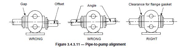
Because rotary pumps are designed with close running clearances, clean piping is a must. Dirt, grit, weld bead or scale, later flushed from an unclean piping system, will damage and may seize the pump. Figure 3.4.3.11 illustrates pipe-to-pump alignment considerations.
Piping should be installed on supports independent of the pump. Supports must be capable of carrying the mass of the pipe, insulation and the pumped fluid. Supports may be hangers, which carry the mass from above, or stands, which carry the mass from below.
Clamps or brackets may be used to secure piping to existing columns. Supports must allow for free movement of the piping caused by thermal expansion or contraction. Supports should be installed at intervals that uniformly and amply support the piping load, precluding contact with adjacent piping and equipment. Pipe strains or stresses transmitted to the pump by improper piping support systems may cause distortion, wear or binding of the rotary members as well as excessive power requirements.
Piping systems that contain expansion joints must be designed so the expansion joint is not exposed to more motion than accounted for in its design. Expansion joints or flexible connectors should not be used to compensate for misaligned piping.
Threaded joints should be coated with compounds compatible with, but not soluble in, the pumped liquid. End users working with Teflon-taped joints should be careful to prevent shredded pieces of Teflon from entering the piping system. Piping should start at the pump and work toward the source of supply and the point of discharge. Shutoff valves and unions (for pumps with tapped ports) are recommended to facilitate future inspection and repair. Reducers are preferred to bushings when a change in pipe size is necessary. Avoid unnecessary restrictions in the pipeline, such as elbows, sharp bends, globe or angle valves, and restricted-type plug valves.
Users should predetermine pipe size by taking into account the required flow rate; minimum or maximum velocities; the fluid viscosity at the lowest pumping temperature; the length of the piping system, including valves, strainers and other restrictions; and the elevation of the pump with reference to supply and discharge points.
For additional information regarding rotary pump test procedures, see ANSI/HI – 3.1-3.5
July 2024
- What methods are recommended for measuring a controlled-volume metering pump’s flow rate, and what should be taken into account to ensure an accurate measurement?
- What procedures should be followed to ensure proper testing of controlled-volume metering pumps?
-
What is the difference between a Newtonian and non-Newtonian fluid, and how do different fluid types impact the performance of rotary pumps?
The impact of the fluid type on a rotary pumps is generally viscous related. The viscosity of a fluid is the tendency of the fluid to resist an internal shearing force. The viscosity of the fluid being pumped affects the net positive inlet pressure required (NPIPR) and will impact the pump flow slip.
A fluid is Newtonian when the ratio of shear stress to shear rate is a constant for all shear rates, is independent of time, and zero shear rate exists only at zero shear stress (see Figure 1). Most mineral oils at temperatures above the cloud point (the temperature at which the oil begins to appear cloudy), solvents and water approximate this condition and are considered Newtonian fluids. The viscosity of these fluids is independent of rate of shear.
A non-Newtonian fluid will change viscosity with changes in the rate of shear applied to the fluid and/or the length of time at shear.
Several types of non-Newtonian fluids are defined in Figures 2 through 6.
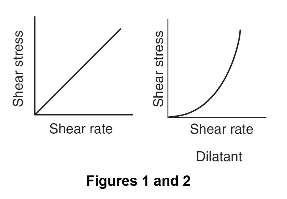
 When the ratio of shear stress to shear rate increases as shear rate increases, reversibly and independent of time, a fluid is said to be dilatant (see Figure 2). Highly concentrated pigment-vehicle suspensions—such as paints, printing inks and some starches—are dilatant fluids. The apparent viscosity of these fluids increases as the rate of shear increases. Some dilatant fluids solidify at high rates of shear.
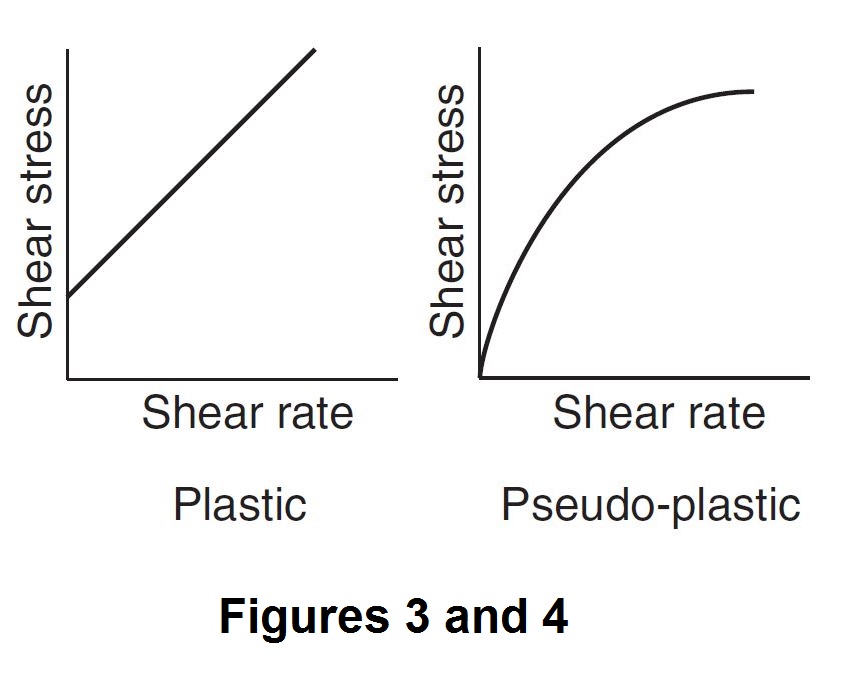
When the ratio of shear stress to shear rate is constant for shear rates above zero, it is independent of time, but when shear occurs only for shear stress above a fixed minimum greater than zero, a fluid is termed plastic. A plastic fluid, such as putty or molding clay, is characterized by a yield point. This means that a definite minimum stress or force must be applied to the fluid before any flow takes place.
When the ratio of shear stress to shear rate decreases as shear rate increases, reversibly and independent of time, and zero shear rate occurs only at zero shear stress, a fluid is pseudo-plastic. Many emulsions, such as water-base fluids and resinous materials, are pseudo-plastic fluids. Their apparent viscosity decreases with increasing shear rates but tends to stabilize at high rates of shear.
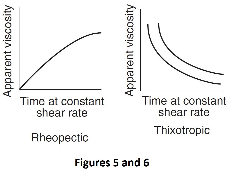
A fluid is thixotropic when the ratio of shear stress to shear rate decreases and is time-dependent in that this ratio increases back to its “rest” value gradually with lapse of time at zero shear rate and stress, and decreases to a limit value gradually with lapse of time at constant shear rate. Most greases, drilling mud, gels and quicksand are thixotropic fluids when the apparent viscosity of these materials decreases for an increasing rate of shear and for an increasing length of time at shear.
When the ratio of shear stress to shear rate is constant for all shear rates at any given instant of time, but increases with time, a fluid is rheopectic. Some greases are intentionally manufactured to have partial rheopectic properties that facilitate pumping in a stable condition; however, upon shearing in a bearing, the grease builds up to a higher apparent viscosity.
Additional information about fluids and the effect of viscosity on pump and system performance may be found in ANSI/HI 3.1-3.5 Rotary Pumps for Nomenclature, Definitions, Application, and Operation.
July 2016
-
What are the key considerations for upstream (suction) piping for single and multiple control-volume metering pumps?
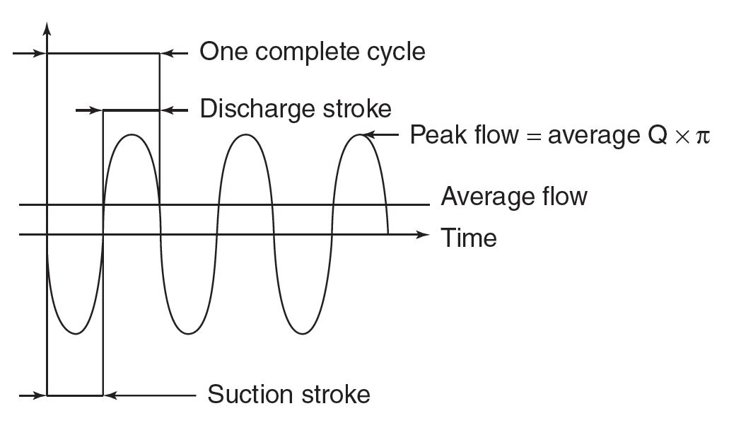
Because of the characteristic pulsating flow of metering pumps (see Figure 7.8.7.1), where peak flow rates can reach three times the average flow, operators must carefully consider suction piping to ensure that it can deliver adequate fluid to the pump inlet.
- The piping must accommodate the peak demands of the pump throughout its full range of operation, as well as prevent off gassing of liquids with high vapor pressure or dissolved gases. This can be accomplished by appropriately increasing the diameter of the suction piping and connections or by adding additional accessories to increase the flow of liquid to the inlet of the pump.
- Long lengths of pipe, elbows, tees, strainers, valves and other accessories installed in the suction piping can decrease the net positive inlet pressure available (NPIPA) to an unacceptable level.
- The pulsating flow in the system suction piping creates a pulse pressure that typically subtracts from system suction pressure. For example, a pump operating at 150 strokes per minute and 71 gallons per hour drawing water from 10 feet of half-inch schedule 40 pipe could subtract 10 pounds per square inch from the pump’s supply pressure. For shorter runs of pipe with minimum restrictions, a general rule of thumb is to increase one pipe size above the discharge piping, or two pipe sizes above the pump’s suction connection. Long piping runs with multiple bends, elbows, restrictions and/or higher-viscosity liquids require larger size piping.
- The most frequent reason for technical support calls to pump manufacturers regarding problems with pump performance is suction piping that cannot supply the demands of the pump. To ensure adequate flow to the inlet of the pump, refer to NPIPA calculations outlined in ANSI/HI 7.8-2016.
When connecting more than one pump head to a single suction manifold, operators must consider a number of issues. Suction manifold piping must accommodate peak demand of the pumps throughout its full range of operation, as well as prevent off gassing of liquids with high vapor pressure or dissolved gases. This is accomplished by appropriately increasing the diameter of the suction manifold and pump head connections or by adding accessories to increase flow of fluid to the pump inlet. The most important consideration is whether the multiple heads are part of a multiplex pump (multiple heads connected to a single motor or driver) or if the heads all have independent motors or drivers. In most cases, multiplex pumps are connected to a common manifold piping arrangement, driving these recommendations. The other option is to connect each pump head to its own suction line connected to the supply source.
In a multiplex where a single driver is used, if the pumps all operate from the same gear set or with multiple gear sets operating at the same stroking speed, industry best practices suggest that the drive mechanism for each individual pump head should be run out of phase (i.e. duplex pumps, 180 degrees; triplex pumps, 120 degrees; and so on). This staggers the peak suction requirements of the individual pumps. Running several pumps from the same driver (motor) with proper phasing of the drive elements to ensure this timing during all running conditions and the best suction flow characteristics as they relate to piping design.
When independent pumps, each with its own driver, are connected to a common suction line, or if the application requires multiplex pump heads operating in phase, operators must make allowance in the piping design in case all pumps simultaneously demand peak suction flow.
For more information on piping guidelines for control-volume metering pumps, refer to the new standard ANSI/HI 7.8 Control-Volume Metering Pump Piping Guideline.
August 2016
Pump Systems
-
How does motor load impact the total pump system efficiency?
Motors, along with pumps, drives, control valves, and piping, are critical components of pumping systems. It is extremely important to understand the relationship between motor efficiency and load in order to maximize the efficiency of pumping systems and reduce costs.
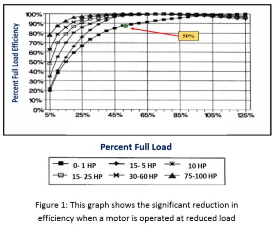
The relationship between motor efficiency and load can be seen in Figure 1, which shows typical motor part-load efficiency as a function of the full load. Generally, at 50% load, a given induction motor will operate very close to its rated efficiency. Above 50% of the full load, the motor will operate at nearly the same percent efficiency. However, reducing the load on a motor below 50% causes the motor efficiency to drop more significantly, which therefore reduces the efficiency of the entire pumping system. The effect operating a motor at reduced load varies depending on the motor horsepower size, as illustrated in Figure 1. Motors that that have a higher horsepower size, such as the larger 75-100 horsepower motors, experience a less drastic reduction in efficiency when operated below 50% of the full load. For smaller motors, such as the 0-1 horsepower motors, the effect of dropping below 50% of the full load is much more drastic.

For additional information related to pump system efficiency refer to HI’s online eLearning pump systems assessment certificate training program at www.pumps.org
January 2018
-
How will pump vibration differ when driven by an engine compared to an electric motor?
Engines do not have the same characteristics as that of a motor drive. An electric motor produces a very smooth torque to drive the load and does so without any reciprocating parts or significantly unbalanced rotating components. Typically, the motor rotor is balanced to a tight tolerance to minimize vibration caused by unbalance forces occurring at the rotating frequency. There may be some slight torque ripple at line frequency (i.e. 50 hz or 60 hz) or higher harmonics of line frequency, but these are typically in a range of one to two percent of mean torque, if they exist at all.
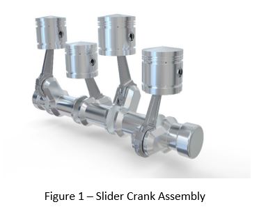
An engine generates torque in a fundamentally different manner than an electric motor. Fuel is burned in a cylinder, and the expanding gas generates torque on a crankshaft through a slider crank mechanism containing a piston and connecting rod, as seen in Figure 1.
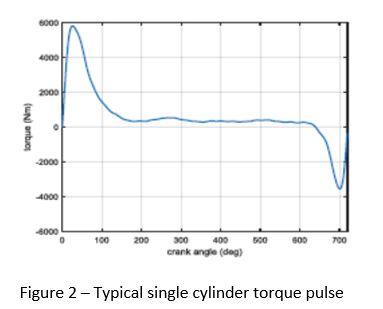
This firing process inherently generates greater vibration levels as compared to electric motor drives because engine generated torque is not smooth. The torque profile depicted in Figure 2 is to how a single cylinder of an engine produces power and is completely normal.
The resulting load on the pump will include both lateral forces at the bearings as well as torque transmitted through the engine coupling. This load versus time is not a smooth sine wave, which can lead to generation of strong harmonics at the firing frequency and it multiples. Furthermore, the cylinder to cylinder combustion process is typically not uniform and in a four cycle engine there are noticeable, and possibly dominate, harmonics at half engine running speed, which can be transmitted to the pump. Generally the pump is designed for these forces and the measureable vibration at the pump bearings are at normal levels, but the number of harmonics and variable speed increase the chance of resonance occurring. In the case of resonance, a normal forced vibration can be amplified and result in excessive pump vibration.
What is the acceptable pump vibration when driven by an engine? This is a common question received, and the answer is not as. The American National Standards, ANSI/HI 9.6.4-2016 Rotodynamic Pumps for Vibration Measurement and Allowable Values standard excludes pumps driven by stationary reciprocating engines. The purpose of HI’s Paper Vibration Characteristics of Stationary Engine Driven
Rotodynamic Pump Systems is to describe stationary engine vibration characteristics and to inform readers that the Hydraulic Institute is working on a data collection project that has an end goal of expanding the scope of ANSI/HI 9.6.4 to include guidance for acceptable vibration limits of rotodynamic pumps driven by stationary reciprocating engines.For more information on engine driven pump vibration refer to the free paper Vibration Characteristics of Stationary Engine Driven Rotodynamic Pump Systems at pumps.org.
December 2020
-
How do I calculate the three-phase input power to a motor?
To calculate the three-phase input power to a loaded motor, three parameters need to be taken into consideration:
- the RMS voltage (the mean line-to-line of 3 phases),
- the RMS current (mean of 3 phases), and
- the power factor as a decimal
In the field these parameters can typically be measured directly by electricians using hand-held instruments or determined from the motor characteristic curve (power factor). With these three parameters, the three-phase power input power to a motor can be calculated by using
Additionally commercial power meters are available that can be installed that measure all these parameters directly including power factor to directly measure the three phase power input to an electric motor.
For more information related to the calculation of electrical input power in the field refer to HI’s Pump Systems Assessment Body of Knowledge at www.pumps.org.
January 2018
-
What should I consider when installing a VFD in a pumping system?
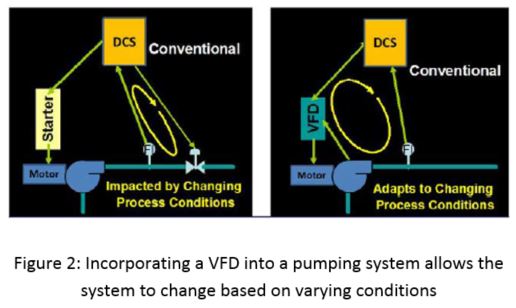
Variable Frequency Drives, or VFDs, are electronic devices that control the rotational speed of an AC electric motor by controlling the frequency and voltage of the electrical power supplied to a motor. When properly applied this reduces the stress on and the energy consumed by the pumping system. As mentioned, VFDs and their controls are crucial elements to the reliability and energy consumption of a pumping system. VFDs can provide controlled starting and stopping of the pumps and through proper feedback control change the speed of a pump to match the system requirements.
Because a VFD controls the speed of the motor, the system can accommodate varying operating conditions, making the entire system more versatile (see Figure 2). These control function can include flow control, level control, pressure control, temperature and control. Additionally, VFDs can provide detection of a prevention of upset conditions such as cavitation, pump deadhead, and dry running adding to their benefits.
Despite all of the advantages of incorporating a VFD into a pumping system, special consideration needs to be taken when programming and installing these devices. There are many different kinds of pumps with different torque requirements, so a VFD must be programmed to provide the correct amount of torque for the given pump system. For example positive displacement pumps have a constant torque load as speed is reduced, which requires special considerations compared to a rotodynamic pumps that is a variable torque load. Another issue that needs to be considered when programming a VFD is that the speed range increases the chance of a pump forcing frequency interacting with a natural frequency of the system; a phenomenon known as resonance.
These are a small portion of the considerations for use of VFDs and variable speed pumping, specific information on installation considerations for VFDs along with other useful information regarding VFDs and variable speed pumping can be found in the HI Guidebooks, “Variable Frequency Drives: Guidelines for Application, Installation, and Troubleshooting” and “Application Guideline for Variable Speed Pumping”.
January 2018
- How can I determine if my pumping system is a good candidate for improved energy efficiency and how do I quantify it?
-
How do I use the information on a pump curve to select a pump for my system?
A pump curve (sometimes called a performance curve) is a graph that shows the total head, power, efficiency and net positive suction head (NPSH) where a 3 percent head loss occurs (NPSH3) plotted against rate of flow. These curves contain extremely important data that pump users need to analyze and interpret for proper pump selection and efficient operation.
There are three main types of pump curves supplied by the pump manufacturer:
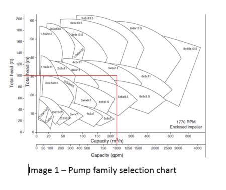
- The selection chart shown in Image 1 (also known as the range chart or the family curves)
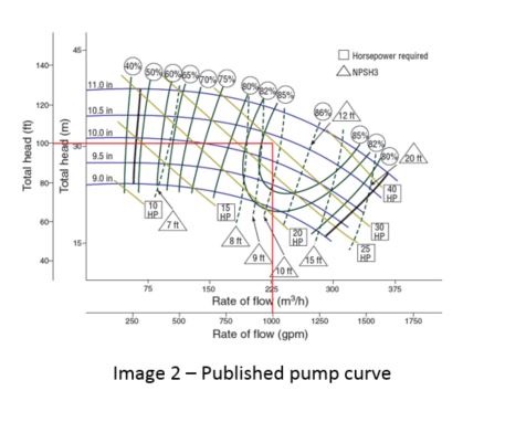
- The published curve shown in Image 2
- The certified curve
 The certified curve is different from the selection chart and published curve because it is for the specific pump and impeller trim purchased and not the general product line. Often it will include the acceptance test standard and acceptance grade that the pump was tested against.
The selection chart shows the various pump sizes available for a given manufacturer’s pump line and speed. The desired head and flow rates are entered on the curve, and the pumps that overlap the area are valid choices to consider for selection. The selection chart is useful in developing a short list of pumps for consideration. For example, if the application called for a pump running at a nominal 1,800 revolutions per minute (rpm), that could provide 1,000 gallons per minute (gpm) at 100 feet of total head, the chart shows that 5 × 6 × 11 and 6 × 8 × 11 size pumps overlap on the selection chart and will likely be the two best sizes to evaluate further.
Although the published curve may seem confusing, a lot of critical information can be extracted from this pump curve. If you understand the charts, you will benefit from the data they offer. Remember:
- The Y axis (vertical) on this curve is the head in feet and meters, and the X axis (horizontal) is the capacity (flow rate) in m3/h and gpm.
- Each of the downward sloping blue lines is called a head capacity curve.
- Each of the numbers above the head capacity curves to the right of the Y axis represents different impeller diameters. As can be seen, the total head is reduced when the impeller diameter is reduced.
- The numbers in the circles above the topmost head capacity curve are the pump efficiency, and the lines stemming from these circles are lines of constant efficiency. The triangles that contain a number and word “NPSH” are constant lines of NPSH (in feet) that the system must supply for the pump to operate with a 3 percent head loss. NPSH margin above this value is required for the pump to operate at the published head (refer to ANSI/HI 9.6.1).
- Finally, the diagonal lines that run through the head capacity curves signify lines of constant pump input power.
Using the selection chart to narrow down the appropriately sized pump for the duty point of 1,000 gpm and 100 feet of head, the manufacturer’s published curves can be referenced to help determine the best pump for an application. Image 3 shows an example of the published curve for a 5 × 6 × 11 pump running at 1,770 rpm. A significant amount of information can be derived from the manufacturer’s pump curve for this application, including the following:
- The impeller diameter that meets the duty point falls between 10 and 10.5 inches.
- The pump is 85 percent efficient at the rated point and 86 percent efficient at the best efficiency point (BEP).
- At the rated point, the shaft power will be between 25 horsepower (hp) and 30 hp; however to ensure a non-overloading condition at the end of curve, a 40-hp motor may be required.
- NPSH3 is between 9 and 10 feet at the duty point.
Note that data displayed on a manufacturer’s pump curve are based on 68 F or 20 C water. If a liquid other than water will be pumped, information on the manufacturer’s published curve must be adjusted for the liquid density and viscosity, which affects the head, flow, efficiency and pump input power.
For more information regarding pump curves, refer to the Hydraulic Institute’s Pump System Assessment Certificate program.
June 2018
- What is an eddy current drive?
-
What is the difference between a grid coupling and a gear coupling?
Flexible couplings can be broken down into elastomeric and metallic types. Both grid and gear couplings fall into the lubricated category of metallic couplings as outlined in Image 1.
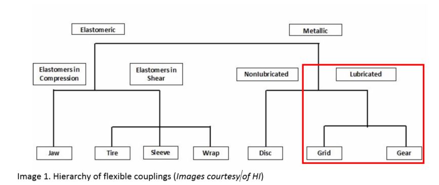
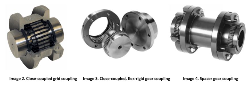
Grid style couplings are often used in medium- to heavy-duty applications and use a spring-style metallic element with looping segments that interlock with the hub teeth. An example of a grid coupling is shown in Image 2. The grid element or spring is made of high tensile alloy steel. The grid element transmits torque and accommodates some misalignment and shock loading in the system. The metallic grid coupling design allows for a more power-dense coupling solution in comparison to elastomeric designs. Because of the relative movement between mating metal surfaces, the grids and teeth must be lubricated as specified by the manufacturer. Typical grid couplings consist of two hubs, two seals, two gaskets, a grid element, and either an axially split or vertically split (perpendicular to the shaft) cover.
Gear couplings come in many different designs, but all transmit torque and accommodate some misalignment through gear teeth. A few examples of gear couplings are shown in Images 3 and 4. Each hub has gear teeth cut around the outside diameter, with the hub connecting to a sleeve with mating gear teeth cut into the inner diameter. These products also require lubrication due to the relative movement of mating metal surfaces and have seals between the sleeve and hubs.
Gear couplings are often used in applications where high torque and balance are required. In some cases, gear couplings are the only solution with enough torque capacity to accommodate demanding applications. There are many custom options available with gear couplings in addition to those described here. This type of coupling can be configured as a flex-flex, flex-rigid or rigid-rigid style gear coupling. A flex-flex configuration uses two flexible style halves, with one half consisting of a flexible hub and a matching flexible sleeve. A flex-rigid style uses one flexible style half and one rigid half. A rigid-rigid gear coupling uses two rigid style halves. Flexible style grid halves also have seals to retain lubrication, and both styles typically incorporate a gasket between the mating flange faces.
For more information on couplings used with pumps refer to HI’s Flexible Coupling Basics Guidebook.
July 2018
- What is the difference between a pressure gauge, pressure switch and pressure transducers?
- What are the different kinds of pumps used at power plants?
-
How can I measure the power consumed by a pump in the field to compare to the manufacturer’s performance curve?
Monitoring a pump system’s performance through power measurements is a great way to evaluate the condition of equipment over time. As noted in the question, pump manufacturers typically publish the power required by the pump as a function of flow rate at a given rotational speed, which does not incorporate losses from other components of the system such as intermediate gears, motors or variable speed drives. The input power to the pump is determined by measuring the torque and rotational speed at a given flow rate, or by measuring the electrical input power to a motor that has been characterized so that the motor input power can be correlated to motor output power (pump input power). Image 1 shows a typical performance curve for a rotodynamic pump. Note that power and efficiency are specific to the pump and not inclusive of the motor used.
If a user is interested in trending the condition of the overall system (pump, motor, gear, etc.), then measuring the electrical input power to the motor or variable speed drive at a given flow rate and rotational speed is sufficient. However, if the focus is monitoring the condition of just the pump and comparing it to the manufacturer’s pump curve, at a given flow rate and rotational speed, there are two options:
- Measure the torque of the pump shaft and its rotational speed.
- Measure the motor electrical input power and incorporate the losses of the motor. If a variable speed drive or other piece of equipment is used in the system, the losses of these components also need to be considered.
When assessing equipment in situ, most of the time it is not practical to directly measure the torque on the pump shaft (although it can be done). Therefore, the second option above is typically the most straightforward approach for in situ measurement of the pump input power. The second option requires measuring the electrical input power to the motor and then correlating the motor input power to the output power. Image 2 is an example of a characterized motor curve (sometimes called a calibrated motor), and this is used to correlate the motor input and output powers.
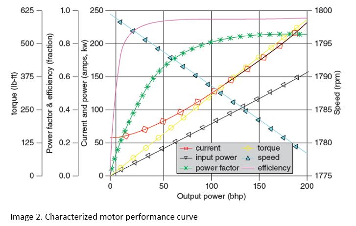
The power meter can be installed in the switch gear to measure the motor input power, or it can be calculated based on several individual measurements with use of the characteristic motor performance curve. As shown in the motor input power equation (Equation 1), motor current and voltage must be measured and power factor must be determined from the characteristic curve to calculate motor input power. To convert kilowatts (kW) to horsepower (hp), divide kW by 0.746. Once the motor input power is measured or calculated the output power can be determined from the characterized motor performance curve.
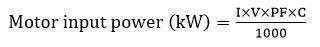 (Equation 1)
Where:
I = RMS current in amperes (A) (meter reading)
V = RMS volts (meter reading)
PF = power factor (motor characteristic curve)
C = 1 for single-phase current
= 2 for two-phase four-wire control
= 1.73 for three-phase current
Because the data displayed on manufacturers’ pump curves are typically based on 68 F (20 C) water at given rotational speed, two additional points to consider are:
- Is the process water-like (i.e. same density and viscosity)?
- If the process fluid is not similar to the water test, the liquid density must be corrected, which affects pump input power linearly with respect to the water density. If the viscosity differs from the manufacturer’s test, the head, flow, efficiency and pump input power will be affected. ANSI/HI 9.6.7 Rotodynamic Pumps – Guidelines for Effects of Liquid Viscosity on Performance should be consulted to adjust the performance for liquid viscosity.
- Is the in situ test speed the same as the manufacturer curve?
- The manufacturer’s performance curve is typically represented at a constant speed. The pump performance will change with pump speed according to the affinity rules. The equations relating the rotodynamic pump performance parameters of flow rate, head, and pump input power, to speed are known as the affinity rules as outlined in Equation 2.
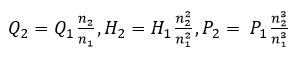 (Equation 2)
Where:
Q2 = rate of flow at desired speed
Q1 = rate of flow at original speed
n2 = desired pump speed
n1 = original pump speed
H2 = total head at desired speed
H1 = total head at original speed
P2 = pump input power at desired speed
P1 = pump input power at original speed
For more information on assessing the performance of pump systems, refer to the Hydraulic Institute’s Pump Systems Assessment Professional (PSAP) Certification Program.
November 2018
-
How much will pump efficiency be affected with the addition of a variable speed drive?
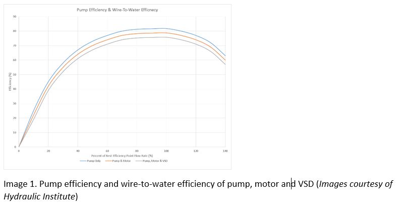
It is a misconception that adding a variable speed drive (VSD) to a pump will increase its efficiency. When considering the wire-to-water efficiency of the pump, motor and VSD, each component that is added lowers the wire-to-water efficiency at a respective flow rate because each component has losses associated with it. Image 1 illustrates this concept showing the pump efficiency being the greatest, then the wire-to-water efficiency decreasing at the respective flow rate when the motor and VSD are added to the extended pump product.
The advantage that the VSD brings to the picture is that it can control the speed of the pump to meet the requirements of the system, which can reduce power consumed by less efficient controls that is not an essential requirement of the process. Additionally, the VSD can be used with on-off controls so the pump operates at a minimum speed where the specific energy consumption is optimized. Based on this, the VSD potentially increases the entire pump system efficiency by eliminating wasted head across control valves and wanted flow through bypass vales, and in some instances allows the pump to operate closer to its best efficiency point (BEP).
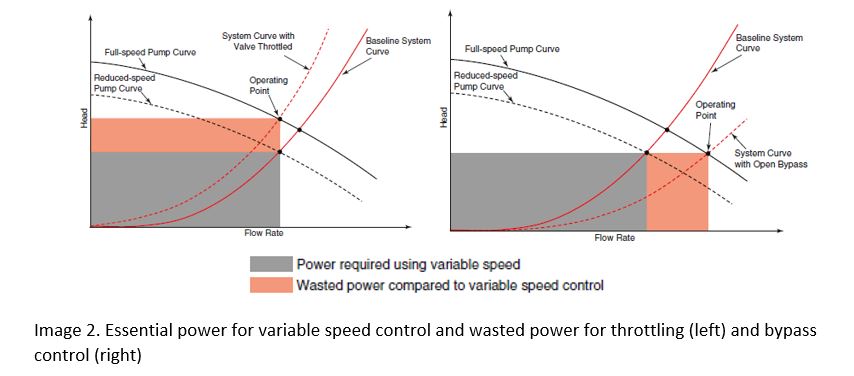
Image 2 illustrates two examples where the gray box represents power that is essential to the system and the orange box represents power that is not essential to the system. The orange box shows how much energy is wasted by throttling control in the first image or bypass control in the second image. In each case the reduced speed pump curve can satisfy the operating flow without the orange wasted control power. The wasted control power typically outweighs the slight decrease in wire-to-water efficiency of the extended product. The two examples in Image 2 show systems with all friction head, and it is understood that the potential variable speed energy savings will decrease when static head is introduced to the system curve.
For more information on variable speed pumping and the application and efficiency considerations, refer to HI’s Application Guideline for Variable Speed Pumping.
December 2018
-
We are updating our building cooling system. It was mentioned that the update would include primary-secondary pumps, what does this mean?
Primary-secondary (P-S) pumping is incorporated into hydronic system designs for a variety of applications. The most frequent application of P-S pumping is used in chilled water systems where there is a need to have fairly constant flow through the chiller evaporator and variable flow through the distribution system. P-S pumping also allows a designer to break up very large, complicated systems into smaller, more manageable subsystems. P-S pumping can also provide different supply water temperatures to each secondary loop without mixing valves.
The fundamental operating principle of P-S pumping lies in the interconnection of the piping loops. Image 1 is a piping schematic where the two pumping loops share a small section of piping, referred to as the common pipe. The common pipe is located between two standard tees that are spaced approximately three pipe diameters in length apart. If the pressure drop in the common pipe is minimized, the flow rate in each loop will be independent of the other.
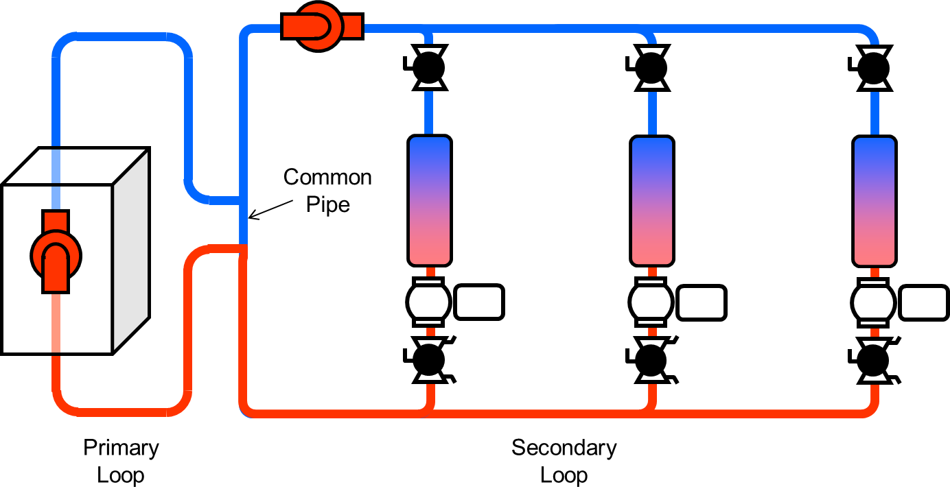
Image 1: Piping schematic of two pumping loops sharing a common pipe
For more information on pumps used in building services, refer to the Pump Application Guideline for Commercial Building Services.
January 2019
-
How can a single variable speed pump be used to control temperature in an HVAC system?
In HVAC systems, there is an opportunity to vary the flow based on heating/cooling demand. The pumping system is designed to supply flow and pressure at the highest system demand. Without control, the pump operates at full speed. This can waste energy and cause wear on itself and other system components.
Operating at full speed when not required creates an artificial demand for cooling in chilled water systems due to higher developed head and flow through the distribution system. Image 2 shows that a temperature input from downstream of a heating/cooling load can be used to slow the pump to the minimum flow required to satisfy the system downstream temperature requirements.
In the case of a variable or staged heating boiler or chiller system, a controller is used to optimize the heating/cooling equipment and the pump flow so the minimum total energy is used to meet the system demand at the heat exchanger.
As illustrated in Image 3, differential temperature can also be used to control the speed of a pump to deliver the flow rate that will maintain a set point differential temperature across a load. This control requires two temperature sensors.
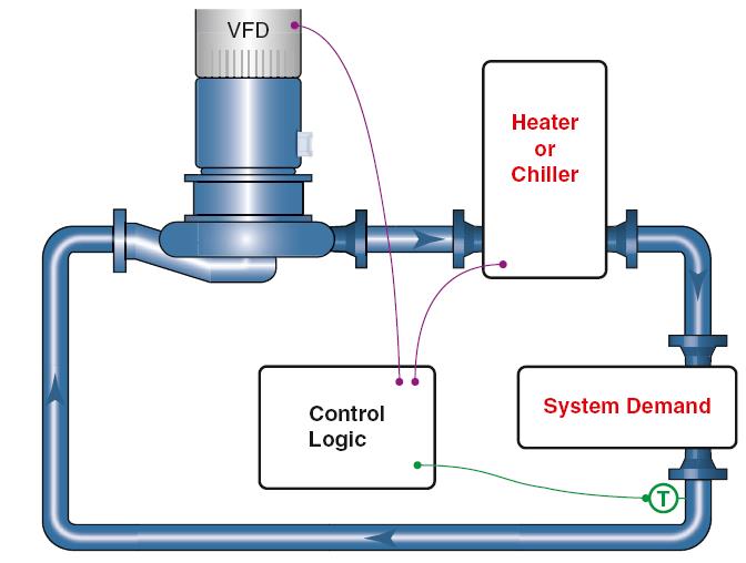
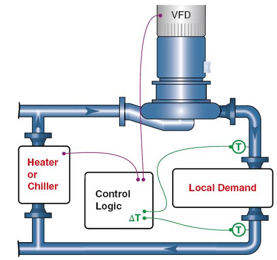
Image 2 – Temperature control Image 3 – Differential Temperature Control
For more information on controlling pumps, refer to Application Guideline for Variable Speed Pumping.
January 2019
-
Why are synchronous motors used for the large pumps in my facility but not small pumps?
A type of electric motor used in pumping applications is synchronous. As the name suggests, the rotation of the shaft is synchronized with the frequency of the supply current. This is different than the most common pump driver, which is the induction motor that has a shaft that rotates at a speed less than the synchronous pole speed.
Synchronous motors have a unique and merited position as the most efficient electrical drive in the industry for slow speed applications. As shown in Image 3, synchronous motors can be applied over a wide range of power and speed but are the preferred driver for low speed and high horsepower applications. They perform with great economy while converting electrical power to mechanical power.
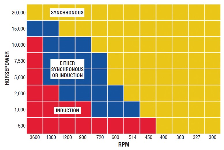
Image 3. Synchronous motor general areas of application
For more information on pumping systems, refer to the newly published guidebook “Pump System Optimization: A Guide for Improved Energy Efficiency, Reliability, and Profitability”.
February 2019
- Our commercial building has many pumps, but I am not clear on what fluids are being handled. What types of fluids are being pumped/handled?
-
What viscosity oil should be used with rolling element bearings?
The viscosity and type of lubricant used will depend on the bearing design and service. Rolling element bearings (Image 1) in process pumps are lubricated by grease, mineral oil or synthetic oil. When selecting a lubricant, it is important to consider that the primary purpose of oil, or the oil constituent of grease, is to separate the rolling elements and raceway contact surfaces, lubricate the sliding surfaces within the bearings and provide corrosion protection and cooling.
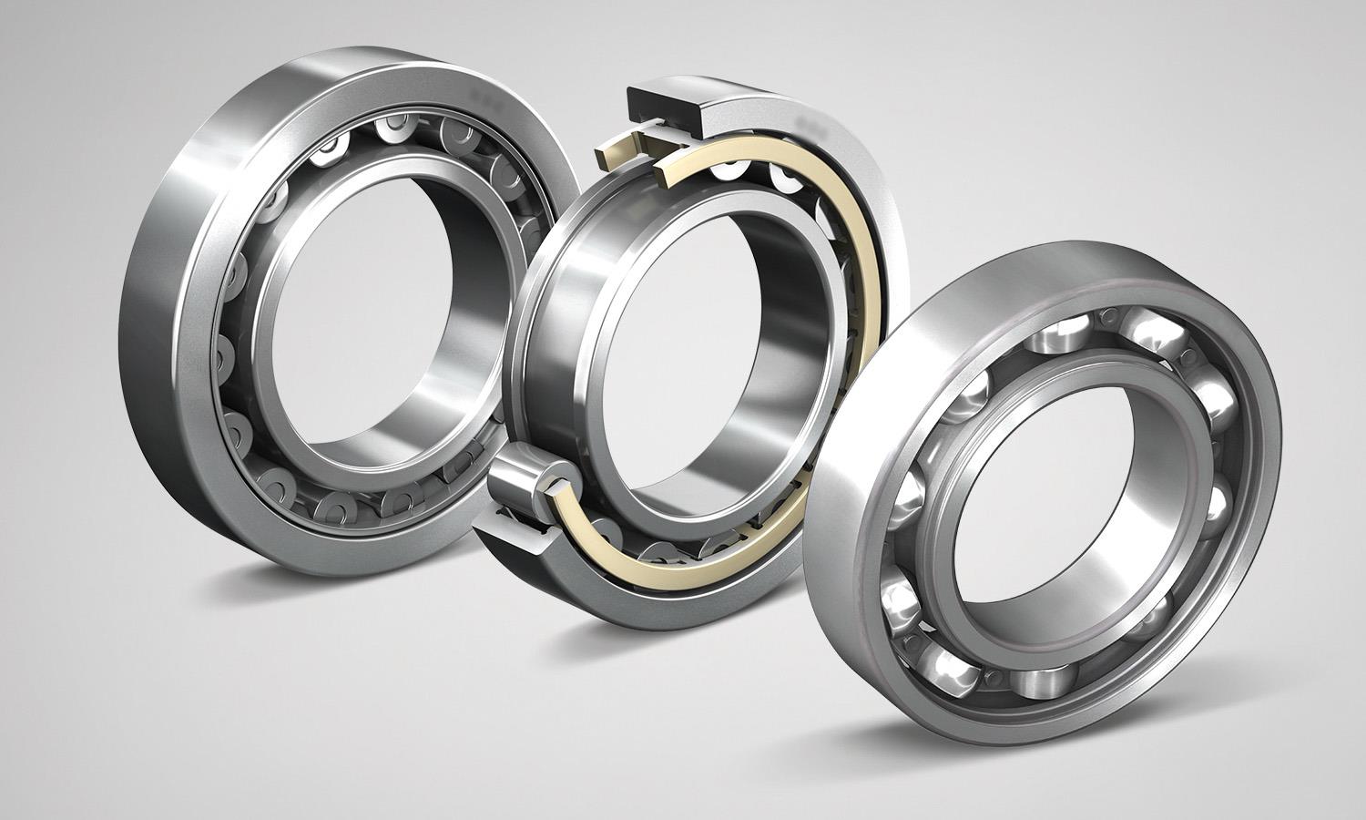
Image 1. Rolling element bearings (Image courtesy of Hydraulic Institute)
Viscosity is an important property of a lubricant, which supports the function of a lubricant in reducing friction and wear. A protective oil film is required to perform these functions. The three basic oil film conditions are referred to as:
- Full film denotes the presence of enough lubricant to ensure complete separation of the moving surfaces. Also known as hydrodynamic full film.
- Elastohydrodynamic (EHD), a hydrodynamic film formed by applied pressure or load. Predominantly found in rolling element bearings.
- Boundary layer is sometimes referred to as thin film lubrication and is usually the result of insufficient lubricant supply. Although lubrication is present, there is not enough to prevent metal-to-metal contact.
Oil or grease base viscosity selection is influenced by load, temperature and speed. If an application involves high speeds, low loads and low temperatures, then a low viscosity lubricant is adequate. Conversely, if low speeds, high loads and high temperatures are the parameters, then a high viscosity lubricant should be chosen.
Oil in process pumps are typically an ISO grade 32, 46, 68 or 100. These numbers relate to the kinematic viscosity in centistokes. The oil can be hydrocarbon oil, although synthetic oils are used for specific lubrication applications. The viscosity of synthetic oil is less sensitive to temperature changes, and more widely used when temperature fluctuations exist. If temperature also exceeds 100 C (212 F), a synthetic is recommended because the oxidation rate of mineral oil accelerates at higher temperatures.
Use of the correct viscosity lubricant for the speed, temperature and loads ensures the development of a full oil film between rotating parts. The optimum fluid film is sufficiently thick to allow the rolling elements to function without metal-to-metal contact with minimum friction. The functionality of the lubricant is negatively affected when the incorrect viscosity is used.
When viscosity is too low, it can cause mixed or boundary lubrication with resulting heat generation and component wear. Excessively high viscosity will prevent metal-to-metal contact, but will generate unnecessary heat and loss of power as the rolling elements are forced to plow through the oil film.
June 2019
- When is grease used as a bearing lubricant?
-
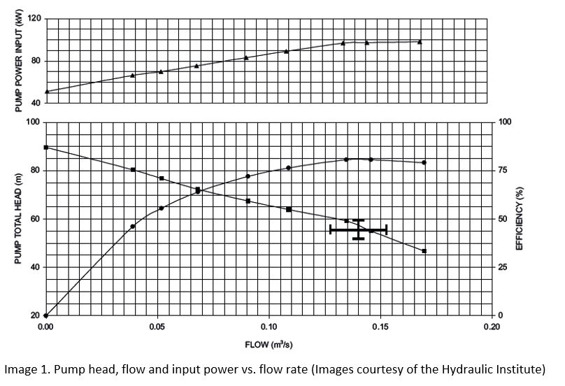
What effect does pumping a high viscosity fluid have on the pump system?
When a highly viscous liquid such as a heavy oil is pumped by a rotodynamic pump, the performance can be significantly changed in comparison to performance with water, due to increased losses. This performance reduction can be estimated by applying correction factors for head, rate of flow and efficiency to the performance with water. These correction factors determine the head and efficiency curves for the pump when handling viscous liquids.
Viscous correction factors are defined as follows (CH for head, CQ for flow, and Cη for efficiency):
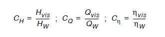
These correction factors are used to correct the water performance to viscous performance. The ANSI/HI 9.6.7 Rotodynamic Pumps – Guideline for Effect of Liquid Viscosity on Performance establishes these correction factors based on empirical data for viscosities up to 3,000 centistokes (cSt), but allows the procedures to be used up to 4,000 cSt with increased uncertainty. The correction factors are based on the “B” parameter calculation which considers the viscosity of the fluid, pump total head, flow rate at best efficiency and the speed of rotation.
Image 1 is an example of water test data for total head, power and efficiency with respect to flow rate corrected for the viscous liquid that will be used in the process. Note that head, flow and efficiency will decrease with the increased viscosity, and the pump input power will have a corresponding increase.
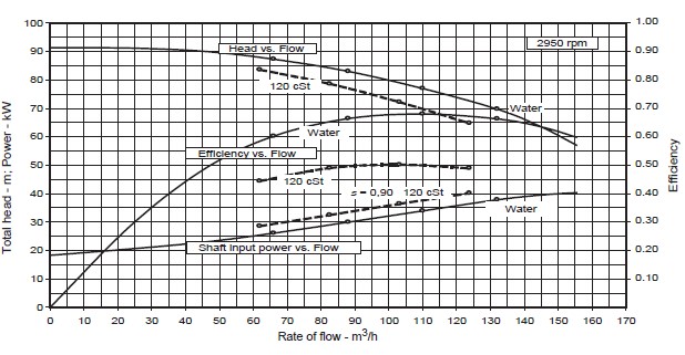
Image 1. Example performance chart for single-stage rotodynamic pump (Image courtesy of Hydraulic Institute)
For positive displacement (PD) pumps, this same relationship is not applicable. The physics of how PD pumps and rotodynamic pumps operate is different. PD pumps will behave differently than rotodynamic pumps handling viscous liquids. Rotodynamic pumps have an impeller that increases the velocity of the liquid to induce flow, but PD pumps capture a volume of liquid and transfer it directly every revolution of the shaft. In PD pumps, a certain amount of volume of liquid will leak (called slip) to a lower pressure region. Increased viscosity can reduce the amount of slip, which can result in increased output flow per shaft revolution, and an increase the volumetric efficiency of the PD pump. This increase in volumetric efficiency is offset by other mechanical and friction losses. The PD pump manufacturer should be consulted about the predicted or actual viscous performance characteristics.
For more information on the viscous performance of rotodynamic pumps, refer to ANSI/HI 9.6.7.
October 2019
-
What are some important considerations when converting an old packed pump to one with a mechanical seal, in the chemical process industry?
The selection of seal chamber design and seal arrangement is based on requirements to maintain a proper environment for the mechanical seal. Factors to consider include normal operation, start-up and shut-down conditions, and standby. Venting of vapors is important where the connection must be at the highest point to ensure a vapor free condition for the mechanical seal. Various pumps are equipped with seal flush and piping plans based on applications and pump types. Refer to Hydraulic Institute Mechanical Seals for Pumps, Application Guidelines for complete information on this topic.
ASME/ANSI B73.1, Specification for Horizontal End Suction Centrifugal Pumps for Chemical Process; B73.2 (Vertical In-Line); and ISO 3069/DIN 24 960 Type C specify several seal chamber dimensions for general service pumps. New pump designs or upgrades should comply with those dimensions to maximize the choices of commercially available seal designs already developed and tested for those dimensional envelopes.
There has been an effort to upgrade pumps originally designed for packing to accommodate mechanical seals; however, the interchangeability in the conventional stuffing box originally designed for packing results in a compromised mechanical seal design (Image 1). Generally, there is inadequate removal of seal-generated heat, greater wasted space and overhang, vulnerability of seal damage under off-design pump operation, vulnerability of seal damage form abrasives, and seal installation difficulties with dual arrangements.
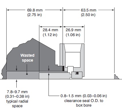
Image 1 – Single mechanical seal mounted in a conventional process pump stuffing box
Improvement 1 – Enlarged Cylindrical Bore
An enlarged cylindrical bore seal chamber offers some solutions to the shortcomings of the conventional stuffing box. A typical single seal installed in an enlarged cylindrical bore seal chamber is illustrated in Image 2. This seal chamber design eliminates the wasted space between the seal and the bottom of the seal chamber, provides more radial clearance over the seal OD, and can provide more axial distance outside of the seal chamber for dual seal arrangements.
The enlarged cylindrical bore design offers an advantage in regards to the thermal system as well.
If the radial clearance above the seal is increased to a point where the seal chamber acts more like a large fluid reservoir than an annulus, and the pump throat is enlarged so that fluid can move in and out of the pump casing, then a single seal can perform satisfactorily with no flush.
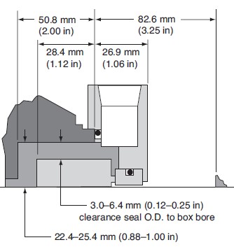
Image 2 – Single mechanical seal mounted in an enlarged cylindrical bore process pump seal chamber
Improvement 2 – Enlarged Tapered Bore
Enlarged tapered bore seal chambers offer the same solutions as enlarged cylindrical bore seal chambers plus they provide static self-venting and allow more complete process fluid drainage during pump shutdown. A typical single seal installed in an enlarged tapered bore seal chamber is illustrated in Image 3. Enlarging the seal chamber bore as shown in Image 3 with a tapered bore results in the low seal face and seal chamber temperatures. This type of seal performance will yield extended seal life. Tapering the seal chamber bore also encourages self-venting of any gases produced within the seal chamber to prevent them from detrimentally affecting seal operating performance.
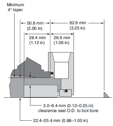
Image 3 – Single seal mounted in an enlarged tapered bore process pump seal chamber
For more information about seal chambers for chemical process pumps, refer to HI’s Mechanical Seals for Pumps, Application Guidelines.
March 2020
-
How does discharge piping impact pump performance and reliability?
A pump’s outlet (discharge) piping flow characteristics normally will not typically affect the performance and reliability of a pump, with a few exceptions. In some cases, sudden valve closures can cause excessively high pressure spikes (surge or water hammer) to be reflected back to the pump, possibly causing damage to the pump, system piping or components.
When the flow of liquid is suddenly stopped, the liquid tries to continue in the same direction. In the area where the velocity change occurs, the liquid pressure increases dramatically due to the momentum force. As it rebounds, it increases the pressure along the pipe near it and an acoustic pressure wave is formed.
This is analogous to the waves on a pond after a stone is dropped in. The waves radiate outward in all directions. As the wave travels further from the center, its energy is spread over a larger and larger area and it will dissipate and eventually die out. In a pipe, the acoustic pressure wave can only travel along the pipe. The potential magnitude of the pressure wave can be tremendous, so in systems where there may be a sudden closure of a check valve or sudden stopping of the pump, a transient flow analysis may be required.
Additionally, the discharge piping of a pump system is a primary source of friction. This will impact the pump system curve, which is a representation of the head required to deliver a specific flow through the system (i.e., the head required from the pump). System curves have a static head component that is made up of elevation difference or pressure difference between the source and the destination. The static component of the system curve is typically independent of the flow velocity in the piping system, however, the friction head component is dependent on the flow velocity in the piping system. Since the friction head component is dependent of the velocity in the piping, the discharge piping size is a leading contributor to friction head, along with fittings and valves in the system.
Image 1 shows a typical pump system curve with the static and frictional components. Take note that the frictional component increases approximately with the squared relation to flow rate (i.e., velocity), and the curve becomes steeper when a valve is throttled (i.e., more friction). This is important because the pump will operate at the intersection of the pump curve and the system curve so if the system requires additional or less head—pressure—than the pump was selected for, the pump may operate at low flow rate or high flow rate, which impacts the pump’s overall reliability.

IMAGE 1: Pump curve and system curves showing static head and friction head
For more information on frictional head loss and pump system curves refer to the HI Data Tool.
July 2025
-
How do throttling valves affect the system curve?
Passive valves, or throttling valves, have a fixed position and do not change their loss coefficient in response to other system changes. These are manually set and do not react to pump and system changes. Since these passive valves are fixed over a range of system flows, they affect the system curve as they are changed.
Changing the valve position will also change the system curve. As the valve is closed, the system curve will become steeper due to the increased loss across the valve. If the pump curve remains unchanged, then with the new system curve, one can predict a new operating point for the pump and flow rate through the system. Image 1 depicts a passive throttling valve and its effect on the system curve. The pump will now need to produce more head to overcome the increased system loss and will move back to a point where it will balance the flow rate and head of the system, in this case at a lower flow rate.
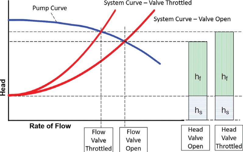
IMAGE 1: Pump curve and system curves showing static head and friction head (Images courtesy of Hydraulic Institute)
Different than passive valves, control valves are not considered part of the system curve. In this case, the control valve actively changes its position and loss, reacting to pump and system changes, to maintain its set point and constrains the system to be at a set flow rate, pressure, level or temperature. The active control valve is not part of the system curve because they are continuously varying their head loss (hCV) and do not have a unique value over the range of system flows. They are, however, represented on the pump versus system plot as the difference between the head produced by the pump at the set flow rate and the head loss of the system also at that flow rate.
Image 2 shows an example of a pump versus system curve with a flow control valve. In this case, changes to the system curve (e.g., tank level changes, other devices opening or closing) would result in the loss across the control valve (hCV) changing. This would not change the operating point of the pump (unless the control valve fails) because the flow rate in the system is being set by the control valve.
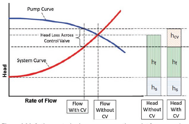
IMAGE 2: Active control valve moves operation point from pump/system curve intersection.
For more information about pump piping and system valves, refer to ANSI/HI 9.6.6 Rotodynamic Pumps for Pump Piping and Guidebook Pump System Optimization: A Guide for Improved Energy Efficiency, Reliability, and Profitability.
May 2020
-
What factors affect pump efficiency?
Perhaps the most important factor is to select a pump that is properly sized for the normal system operating conditions, because off design flow rate will result in lower operating efficiency. Assuming proper hydraulic selection, the first consideration is type or design of the pump. Focusing on rotodynamic pumps, there are many types with different configurations and features to meet specific service conditions—e.g., paper stock, sewage, slurries, etc.—all of which have compromises in design needed to address special applications. This will result in compromise efficiencies compared to clean liquid pumps. Image 1, from HI 20.3 illustrates considerations for slurry and solids handling pumps that will compromise efficiency compared to clean water pumps.

IMAGE 1: Pump efficiency factors (Image courtesy of Hydraulic Institute)
Pump type and design is only the beginning. Another consideration is the pump’s specific speed. Specific speed is an index for the pump design that relates to how the flow enters and exits the impeller. There is an optimal specific speed to reach maximum attainable efficiency that may vary depending on the pump design. However, it may not be possible to select a pump at the “optimal specific speed” because the application will generally dictate the specific speed for the pump. Pumps with a low specific speed discharge flow in a radial direction. Radial flow pumps (low specific speed) produce relatively higher head and lower flow rates. On the opposite end, pumps with higher specific speed, have flow enter and exit the impeller (propeller) in the same axial direction. Axial flow pumps (high specific speed) produce relatively higher flow rate and lower head.
Pumpage is also an important consideration. The viscosity of the pumped fluid will have a detrimental effect on efficiency for rotodynamic pumps. For rotodynamic pumps, the performance as tested on water is corrected to the viscous performance using ANSI/HI 9.6.7 Rotodynamic Pumps – Guideline for Effects Liquid Viscosity on Performance. While this is not an exhaustive list, these considerations are important when estimating the efficiency of your pump.
July 2020
-
Is it really worth buying the more expensive, efficient pump over a cheaper, less efficient pump?
The initial purchase and installation cost of a new pumping system is a small portion of the lifecycle cost of the pump, which typically lasts 15 to 30 years. It is the routine operating costs of energy, maintenance and other recurring expenses that make up the primary components of total life cycle cost (LCC) as illustrated in Image 1 for a typical installation.
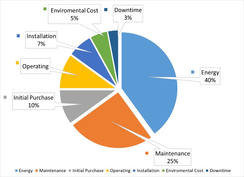
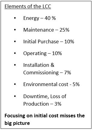
IMAGE 1: Example of life cycle cost for a typical pumping system (Images courtesy of Hydraulic Institute)
For example, say the initial purchase and installation cost of a 100 horsepower (hp) pump was $30,000. The 100 hp pump running at full load with a cost of electricity of eight cents per kilowatt hour ($0.08/kWh), operating continuously would total $52,000 per year. In just one year, the energy cost is more than double the installed cost. Over a typical lifecycle of at least 15 years, the energy cost totals to $780,000. In this example, the installed costs account for only 4 percent of the lifetime energy costs.
To compare a more efficient pumping system’s annual cost, we will assume some round numbers and focus on just the pump input power (excluding the motor) for calculation simplicity. Start with a pump that is 70 percent efficiency and compare it to an identical pump that is 75 percent efficient. This change lessens the pump input power required. This difference can be calculated using the following formula.
Where:
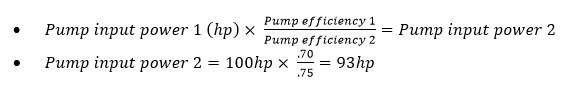
From this calculation we observe a power savings of 7 hp. To calculate the lifetime cost savings of 7 hp, use the following formula.
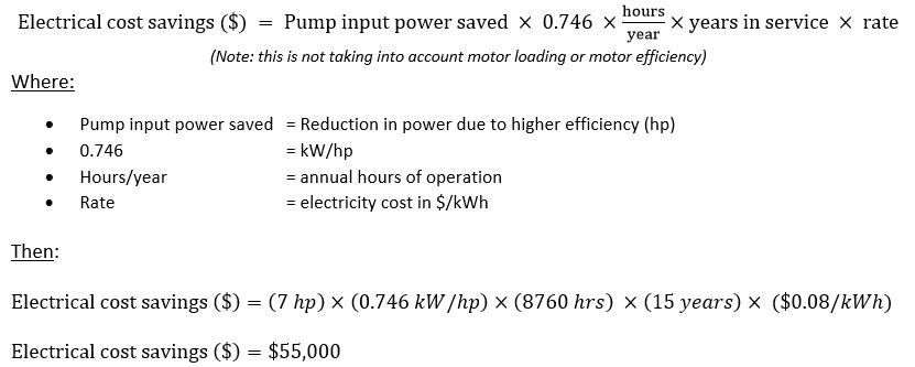
It is important to also note that that pump operating efficiency is often lower than the rated condition due to oversizing, problems with control valves, poor installation and other factors that result in the pump operating away from the best efficiency point or rated condition. Therefore, it is beneficial to precisely analyze the system requirements, optimize the control systems, and when justified by a life cycle cost analysis, invest money upfront for a more efficient pumping system.
August 2020
-
What are common problems that cause excess pump system vibrations?
Pump vibration is related to the pump’s rotational and hydraulic forces, and the dynamics of the pump’s rotor and structure. Typical forced vibration from the pump are related to the speed of rotation in rotations per minute (rpm) and multiples of rpm, such as:
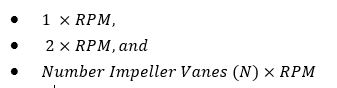
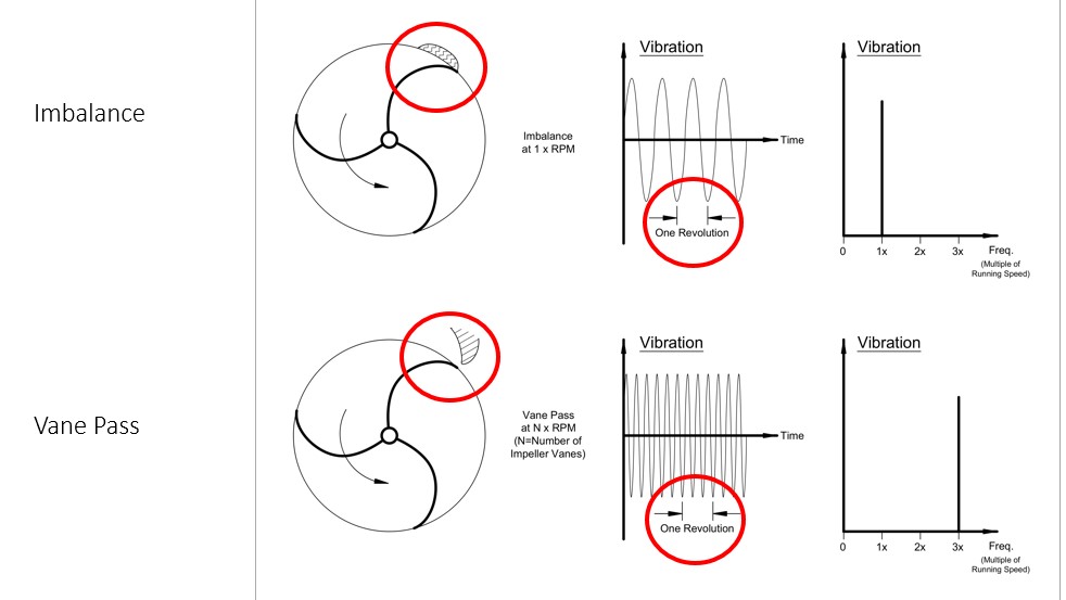
IMAGE 2: Illustration of forced vibration due imbalance and vane pass occur at 1 X RPM, and N X RPM
Some causes for these forced vibrations are misalignment of the pump and driver shaft, imbalance, bent shafts, damaged impeller vanes and many others. The vibration sources can come from system related issues such as cocked or damaged bearings, and inadequate piping supports and other sources of excessive nozzle loading.
Vibration can increase in severity when improper installation and foundation exits, such as improper grouting, inadequate tie-down bolts, inadequate baseplate material, inadequate baseplate rigidity and the lack of proper internal locking of the baseplate to the foundation.
Another consideration is that resonance can occur. Resonance is a condition where of the forced vibration frequency aligns with a structural or rotor natural frequency resulting in amplified vibration. In these cases, even low forced vibration can result in an amplified vibration that is unacceptable. When resonance results in undesirable vibration, the frequency of the forced vibration will need to be changed or avoided, or the natural frequency of the system will need to be modified.
For more information on optimizing pumping systems and pump vibration refer to HI’s Pump System Optimization Guidebook, ANSI/HI 9.6.8 Rotodynamic Pumps – Guideline for Dynamics of Pumping Machinery, and ANSI/HI 9.6.4 Rotodynamic Pumps for Vibration Measurements and Allowable Values.
August 2020
- What pump selection considerations are needed to handle wastewater?
General Pump Standards
-
What is the BEP and what happens to a pumping system when a pump is not operated at the BEP?
The BEP, or Best Efficiency Point, is the point at which the pump operates at peak efficiency. At the BEP, flow enters and leaves the pump with a minimum amount of flow separation, turbulence, and other losses. The closer a pump operates to its BEP, the less wear the pump will experience, which increases the reliability of the pump. In the below image, the BEP is located at the apex of the pump efficiency curve (green line). If a vertical line is drawn from the BEP down to the pump curve (black line), the head and flow rate at the BEP can be determined by looking at where this line is in relation to horizontal and vertical axes.
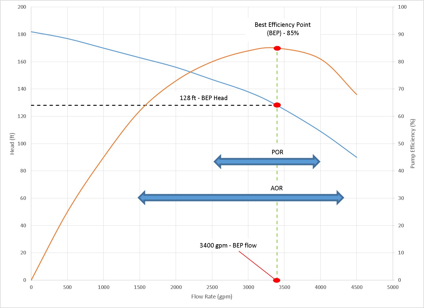
Figure 1: BEP illustrated on head capacity curve with corresponding POR and AOR
A closely related topic to the BEP is the Preferred Operating Region, or POR. The POR is a range of rates of flow to either side of predicted BEP within which the hydraulic efficiency and the operational reliability of the pump are not substantially degraded. Within this region, the design service life of the pump will not be affected by the internal hydraulic loads or flow- induced vibration. Operating a pump within the POR ensures higher reliability and lower energy consumption. A typical range for the POR is shown on in Figure 1. Note that the POR is defined in ANSI/HI 9.6.3 Rotodyanamic Pumps Guideline for Operating Regions, and the POR changes depending if the pump radial (centrifugal), mixed or axial flow type.
A wider range of flows, outside the POR, over which the service life of a pump is acceptable, is designed the Allowable operating region (AOR). The limits to AOR are determined by requirements other than energy consumption and should defined with the help of the pump manufacturer. Some factors that determine the AOR are:
- Hydraulic loads (bearing life, fatigue, mechanical contact, shaft deflection, thrust, etc.)
- Liquid temperature rise
- Bearing housing or shaft vibration
- Audible Noise
- Power limitations
- Net Positive Suction Head
- Suction Recirculation
There are a multitude of negative consequences that arise when a pump is operated significantly above or below its BEP that can result in accelerated pump wear and premature failures. For example operating at excessively low flow rates could cause higher radial loading on the impeller causing excessive shaft deflection leading to premature seal failures. At excessively high flow rates the pump’s required suction head may not be met and the pump could cavitate.
For more information on pump operation see HI’s eLearning certificate course on pump systems assessments and ANSI/HI 9.6.3 Rotodynamic Pumps Guideline for Operating Regions.
February 2018
-
What is the difference between inside-mounted and outside-mounted mechanical seals?
Two categories of single mechanical seals are (1) inside-mounted and (2) outside-mounted. The primary difference between the two styles is that inside mounted seals are contained within the equipment seal chamber and outside-mounted seals are mounted external of the equipment housing. See Figures 2 and 3 for diagrams of an inside-mounted and outside-mounted single seal.
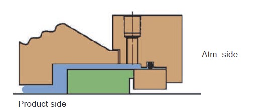
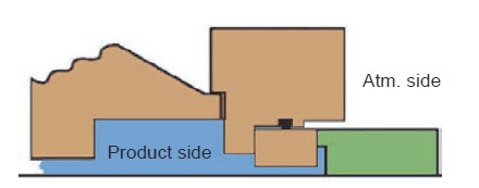
Figure 2 – Inside mounted seal Figure 3 – Outside mounted seal
Some advantages of the inside-mounted mechanical seals are:
- Inside seals are available in a wide variety of materials and designs.
- centrifugal forces tend to reduce leakage,
- catastrophic leakage is usually avoided during seal failure.
One disadvantage of inside-mounted seals is that they can be more difficult to install and maintenance usually requires disassembling the equipment.
Some advantages of outside-mounted seals are:
- The installation is typically easier than with inside seals,
- adjustments can be made without complete equipment disassembly,
- the seal can often be backed-off for cleaning,
- less expensive components can be used for outside-mounted single seals because fewer components are exposed to the product.
One disadvantage of outside-mounted seals is that they usually have lower temperature and speed limits than inside-mounted seals due to lack of sufficient heat removal from the seal faces.
February 2018
- How do I determine if a motor is suitable for use with a variable frequency drive?
-
What is the difference between NPSHR, and NPSHA, and why is it important to know these terms as a pump engineer?
All pump users should be familiar with these terms because supplying a pump with insufficient net positive suction head available (NPSHA) compared to the net positive suction head required (NPSHR) will result in cavitation. Cavitation is the formation of vapor bubbles of the pumped liquid, when the pressure of the pumped liquid drops below its vapor pressure and later the pressure is increased above its vapor pressure, resulting in the rapid collapse of the pockets of vapor. The vapor implosions can cause serious damage to the pumping system and typically noise and vibrations can be noticed.
NPSHA is the total suction head at the inlet of the pump and is a function of the following attributes of the pump and piping system:
- Elevation difference between the liquid level and impeller eye
- Pressure on the surface of the liquid
- Head loss in the pump’s suction pipelines
- Flow velocity at the pump suction nozzle
- Vapor pressure and density of the liquid being pumped
- Barometric pressure at the pump site
NPSHA for a system can be calculated as shown below:
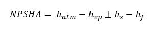
Where:
- hatm is the absolute pressure (in feet of liquid being pumped) on the surface of the liquid supply level. In an open tank, it is the barometric pressure or the absolute pressure existing in a closed tank.
- hvp is the head in feet corresponding to the absolute vapor pressure of the liquid at the temperature being pumped.
- hs represents the static height in feet that the liquid supply level is above or below the pump centerline or impeller eye.
- hf is all suction losses (in feet), including entrance losses and friction losses through pipes, valves, and fittings.
NPSHR is a minimum NPSHA given by the manufacturer which is required for a pump to achieve a specified performance at a specified rate of flow, speed, and pumped liquid. One of the most noticeable effects of cavitation is the degradation of the pump performance due to the presence of the pumped liquid’s vapor phase induced by cavitation. Migration and coalescence of the vapor bubbles affect the flow within the impeller and cause the head developed by the pump to deteriorate. It is important to note that the NPSHR curves historically provided by pump manufacturers may not show sufficient NPSH values to provide zero head loss or to eliminate cavitation. The term NPSH3 has was developed to better describe the industry standard for NPSHR. By Hydraulic Institute definition, the required NPSH of a pump is the NPSH available that will cause the total head (first stage head of multistage pumps) to be reduced by 3%. The required NPSH qualified by this criterion will be referred to as NPSH3. The full published pump head will not, however, be achieved (by definition) when the NPSHA equals the NPSH3 of the pump (see Figures 9.6.1.2b and 9.6.1.2c). The value of 3% head drop for NPSH3 is based on accepted industry practice for defining a condition of head breakdown due to cavitation.
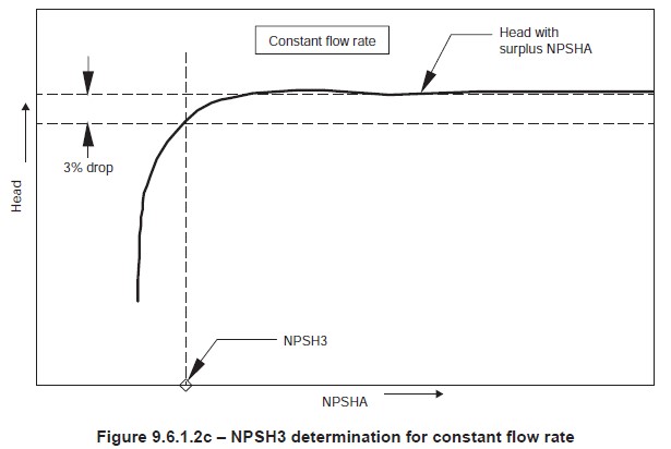
Figure 1 NPSH3 determination for a constant flow rate
For more information regarding cavitation and NPSH, refer to module 2 within the Hydraulic Institute’s Pump System Assessment Certificate Program.
April 2018
- What are some methods for monitoring corrosion in a pump?
- What standards are applied to fossil power plant pumps?
- What types of lubrication can be used for pump bearings?
-
What methods can be used to maintain lubrication oil quantity and quality?
For oil bath lubrication, quantity of oil can always be adjusted by adding oil to maintain the manufacturer’s recommended level. However, another approach to maintain the proper quantity of oil is with bearing housing seals. When properly applied, bearing seals can eliminate lubrication leaks from the housing and help maintain recommended oil levels.
Examples are lip seals, labyrinth isolators and magnetic face seals shown in Image 1. These mentioned seals are also useful in the reduction of oil contamination to maintain the quality of the oil.
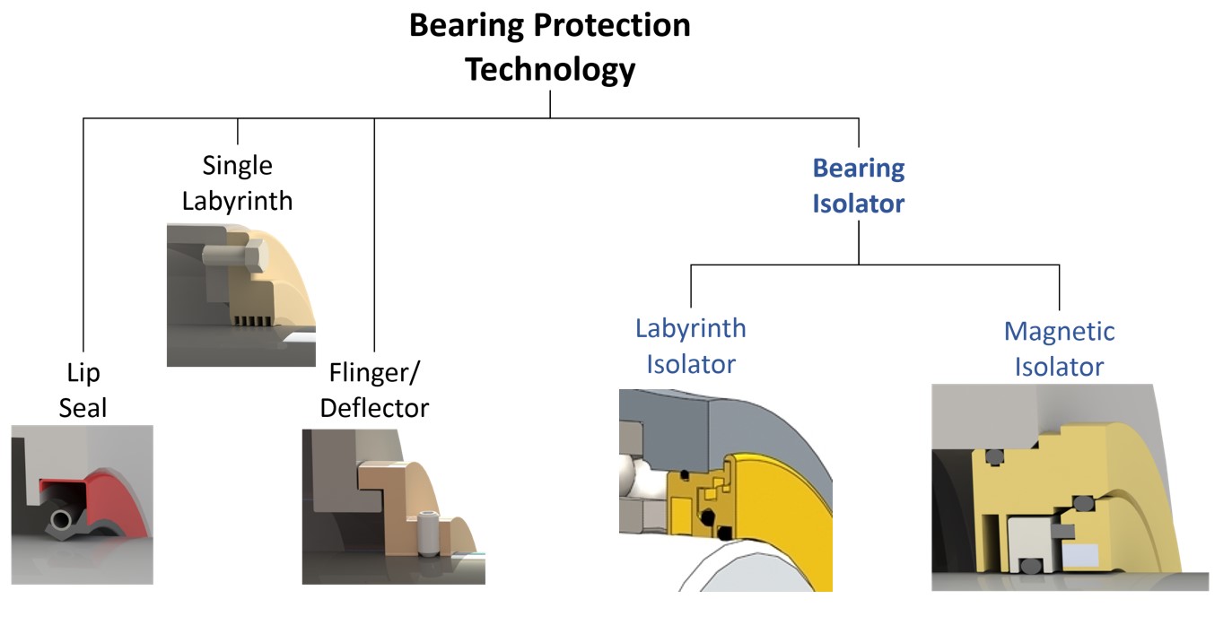
Image 1. Common bearing housing seals (Images courtesy of Hydraulic Institute)
Particle contamination can be avoided by careful consideration of the materials, design and maintenance of lubricant containers, seals and bearing isolators. When selecting and maintaining gaskets and seals, all materials should be compatible with the lubricant. When filling the bearing housing, the fill port should be cleaned prior to opening, the lubricant container should be closed until filling, and care should be taken to prevent atmospheric contaminants from entering the fill port during the fill process.
In addition to preventing lubricant leakage, bearing housing seals also serve to prevent contaminant ingress.
Focusing on isolator technology, labyrinth and magnetic face-type bearing isolators are widely used on pumps. Bearing isolators allow increased pressure created in the bearing housing by normal pump operation to vent through the isolator and have proven to be effective at reducing, and sometimes eliminating, contaminant ingress. The face design and the labyrinth design allow for the venting to occur while in operation. The face design of the magnetic isolator protects the bearings against contaminants while the pump is shut off or in standby using the contacting faces. Labyrinth isolators may use shut-off features to provide ingress protection when the equipment stops rotating as shown in Image 2. These shut-off devices are designed to prevent moisture from penetrating the bearing chamber when the equipment shuts down and air is drawn into the housing.
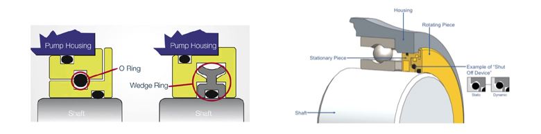
Image 2. Two examples of shut-off devices used in labyrinth seals.
When properly specified, bearing housing lubrication quality-enhancing components—including oilers, bearing protection devices and vents—can be effective in maintaining the quality of bearing lubricants.
For more information proper bearing lubrication and maintaining the quality of the lubrication, download HI’s new freely available white paper Proper Lubrication Methods for Bearings.
March 2019
- How is bearing wear monitored in sealless pumps?
- What are the requirements for uniform flow into a pumps suction?
-
What are methods to detect bearing wear in sealless pumps?
Sealless pumps (canned motor pumps, or magnetic driven) generally have sleeve bearings that are cooled and lubricated by the process fluid. As the name suggests, sealless pumps do not have dynamic shaft seals and are designed so that the rotor is within a containment shell. Excessive wear or failure of the bearings due to insufficient lubrication, abrasives in the lubricant or cavitation, could cause contact between the rotor and the containment device. This contact could result in failure of the equipment and leakage of the process liquid. Therefore, providing some means to monitor the condition of these bearings is desirable. Image 1 provides some common failure methods for sleeve-type (journal) bearings, their causes and indicators.
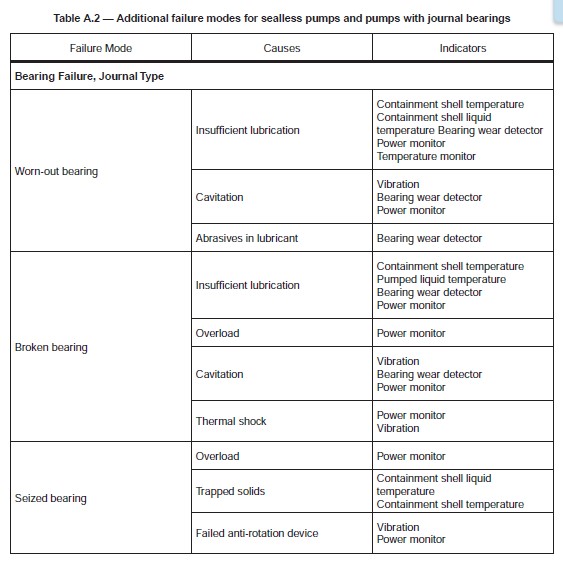
Image 1. Failure modes for pumps with sleeve bearings (Image courtesy of Hydraulic Institute)
The detection method to monitor wear of the bearing depends on the material of the bearings. For instance, silicon carbide bearings are more prone to sudden failure, so a progressive wear monitoring device might not be suitable. Carbon bearings, on the other hand, may exhibit progressive wear, and a progressive wear monitoring device may be beneficial.
With progressive wear monitoring, proximity sensing devices can be used to monitor the position of the rotor within the containment device. Positional changes to the rotor are used to determine the direction and amount of bearing wear. This method allows wear to be detected prior to contact between the rotor and the containment device. The sensing devices should be configured to detect axial and radial changes in the rotor position.
Since bearing wear will cause contact between the rotor and the containment device due to positional changes in the rotor, use of a contact detection device may be useful. Contact can be detected using an acoustic detection device, power monitor, vibration sensor, containment shell temperature probe, continuity probe or contact switch.
For more information about bearing wear detection and seal leakage monitoring, refer to ANSI/HI 9.6.5-2016 Rotodynamic Pumps – Guideline for Condition Monitoring.
August 2019
- How can seal leakage be monitored in submersible pumps?
- How can the proper bearing lubricant be selected?
-
How is cleaning conducted for wastewater and storm water wet wells?
Organic solids accumulations in wet wells will become septic, causing odors, increasing corrosion, and releasing hazardous gasses. The design of a solids-bearing wet well must both provide for proper approach flow to the pumps, and prevent the accumulation of sediments and surface scum in the sump. The main principle is to minimize horizontal surfaces in the wet well anywhere but directly within the influence of the pump inlets, thereby directing all solids to a location where they may be removed by the pumping equipment. Vertical or steeply sloped sides are provided for the transition from upstream conduits or channels to pump inlets.
Trench-type wet wells are designed to provide for cleaning with the periodic operation of the pumping equipment using a special procedure. The standard ANSI/HI 9.8 Rotodynamic Pumps for Pump Intake Design provides guidance on the geometry necessary to induce scouring velocities during the cleaning procedure. Experience has shown that trench-type wet wells with an ogee transition between the entrance conduit and the trench floor provides optimum geometry for efficient cleaning operations.
Trench-type wet wells for solids-bearing liquids can be quickly cleaned by choosing a time when the inflow is about half of the capacity of the last pump. If that pump, operating at full speed, takes more than about a minute to lower the liquid level to the middle of the trench, two pumps can be activated. The liquid flowing down the ramp reaches supercritical velocity and forms a hydraulic jump (see image 1) that, taking all solids with it, moves to the last pump. The hydraulic jump should move from the toe of the ramp to the last pump in no more than 30 seconds, because operation at low intake submergence is severe service for the pump. As the hydraulic jump passes under each upstream pump inlet, the pump loses prime and should be stopped, and will need to be re-primed prior to the next start.
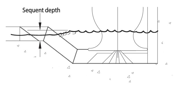
Image 1 – Open trench-type wet-well hydraulic jump
November 2019
-
What drives are used in sealless pumps?
A sealless pump design is one in which the inner rotor assembly is directly driven by either a canned motor or by a synchronous or an asynchronous magnetic drive. In all designs, a portion of the pumped liquid is required in the drive section for lubrication and cooling. The design does not use a dynamic shaft seal as a primary containment device. Static seals are used to isolate the process liquid from the external environment. Since these pumps are designed so that there is no mechanical seal, the chance of the process fluid being released to atmosphere is lessened. Additionally, secondary control or containment can be part of the design, which further lessens the chance of the pumped liquid releasing to atmosphere in the event the primary containment is breached. However, to eliminate the mechanical seal the method for transmitting power to the pump shaft is different than a mechanically sealed pump, as previously mentioned, is achieved with a canned motor or magnetic drive that transmit torque through a primary containment shell.
The canned motor type has a common shaft to link the pump and motor (close-coupled) in a single sealed unit. The pumped liquid is circulated through the motor but is isolated from the stator by a corrosion-resistant stator liner, and is isolated from the rotor by a corrosion-resistant rotor liner.
The magnetic drive type uses an outer ring of permanent magnets to drive an internal rotating assembly through a corrosion-resistant containment shell. This allows magnetic drive pumps to be driven by a standard motor or drive shaft coupled to the magnetic drive. There are two types of magnetic pump couplings: synchronous and eddy current.
Synchronous magnetic couplings contain permanent magnets inside and outside of the containment shell that rotate the pump shaft in synchronized motion with the driver shaft. These couplings do not slip—the pump shaft turns at the same speed as the outer magnet assembly.
Eddy current magnetic couplings consist of a permanent outer magnet ring and an inner torque ring containing a network of copper rods supported on a mild steel core. The rotating magnet ring generates eddy currents in the copper rods, which convert the core to an electromagnet. The difference between the two shaft speeds is defined as magnetic slip.
Synchronous magnetic drive sealless pumps use either ceramic, ferrite, or rare earth magnets, such as neodymium-iron-boron or samarium cobalt. The outer steel portion of the outer magnet assembly should be coated with a corrosion/heat-resistant paint or coating.
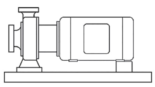
Image 1. OH13i – Magnetic drive, end suction, short coupled (Images courtesy of Hydraulic Institute)
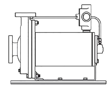
Image 2. OH7i – Canned motor, end suction
For more information about sealless pump drives and vibration analysis, refer to ANSI/HI 4.1-4.6 and ANSI/HI 5.1-5.6, which cover nomenclature, definitions, application, operation, and tests for sealless rotary and rotodynamic pumps respectively.
December 2019
-
How is pump bearing housing vibration measured?
Acceleration transducers (accelerometers) are typically used to measure vibration on stationary components such as bearing housings, but transducers are available and sometimes used that measure velocity. Depending on the reason for the measurement, and frequency range of interest, the acceleration signal may then be integrated to velocity or double integrated to displacement.
Measurements are made in the time domain and then processed and filtered to show the level of vibration occurring at discrete frequencies. The time domain data can be very useful in understanding impacting forces that may be random such as cavitation or other hydraulic events, or periodic impacts such as a broken gear tooth. Image 3 shows a typical time waveform with peak-to-peak, 0-peak, and root mean square (RMS) values.
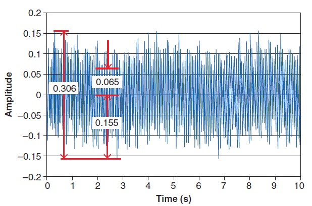
Image 3. Typical time waveform showing peak-to-peak (0.306), 0-peak (0.155), and RMS (0.065) values.
The time domain data is then generally processed and displayed in a frequency spectrum that identifies vibration at specific frequencies. This is convenient to understand what vibration is occurring at known discrete forcing frequencies, such as rotor unbalance, or impeller vane passing frequency. Image 4 shows a cartoon of a frequency spectrum with orders of the shaft frequency called out.
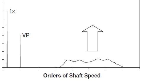
Image 4. Frequency spectrum showing discreet forcing frequencies and high frequency noise
For the purpose of acceptance testing per ANSI/HI 9.6.4 Rotodynamic Pumps for Vibration Measurements and Allowable Values, the measurements are integrated in a circuit to determine the overall RMS vibration. For speeds above 600 revolutions per minute (rpm), the sole measurement quantity to be used for measuring the vibration of stationary parts associated with bearings of rotodynamic pumps is velocity in millimeters per second RMS or inches per second RMS. The measurement instrumentation should be able to measure the RMS vibration velocity for a minimum frequency range of 5 hertz (Hz) to 1,000 Hz. For speeds of 600 rpm and below, the peak-to-peak displacement vibration on bearing housings should be measured in addition to the velocity measurements, and the instrumentation should cover a minimum frequency range of 2 Hz to 1000 Hz.
ANSI/HI 9.6.4 specifies the specific locations for the acceptance testing. In general the vibration transducers should be located approximately at the center of the radial bearing location on bearing housings or the motor mounting flanges of vertical pumps. Transducers must not be located on flexible panels, nameplates or motor end covers.
For more information about sealless pump drives and vibration analysis, refer to and ANSI/HI 9.6.4.
December 2019
-
How is variable speed pumping used in HVAC?
The energy conservation standard for pumps (10 CFR 431 Subpart Y), published in January 2016, recognizes that pumps and motors equipped with variable speed drives (VSDs) can save significant energy and the metrics in the regulation measure this. In heating, ventilating and air conditioning (HVAC) applications of pump systems, the American Society of Heating, Refrigerating and Air-Conditioning Engineers (ASHRAE) 90.1 standard requires water-cooled unitary systems that are greater than 5 horsepower (hp) have a VSD installed on the pump motor. When properly applied, VSDs play a major role in energy conservation. The energy savings in variable flow pumping systems are maximized in systems that are friction dominated, such as water circulating systems for heating and cooling. Image 1 demonstrates the wasted energy that can be saved when the speed is reduced to a lower flow and head in a friction head dominated system.
VSDs allow the pump speed to be lowered or increased, depending on the needs of the system. Reducing the speed of the pump reduces both the pump’s pressure and flow, which reduces power consumption.
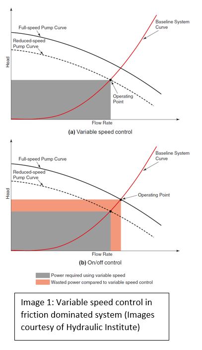
While variable speed control can provide the most efficient, reliable and precise control to meet the system demand, it requires higher investment cost, and it is less suitable for high static or flat system curves, and requires considering mechanical design issues related to resonance, minimum speed and over speed. To justify its use and ensure a reliable installation, it is important to analyze the system’s suitability for the speed range and the benefits of controlling the speed.
To find more information about variable speed pumping, go to 10 CFR 431 Subpart Y, (ASHRAE) 90.1.
February 2020
-
When using variable speed pumping in an HVAC system, should extra precautions be taken to limit the chance of vibration?
In any system that uses a variable speed drive, the chance of amplified forced vibration due to interaction with natural frequencies increases. Forced vibration is due to a mechanical or hydraulic component of the pump. Image 2 shows imbalance and vane pass forces that lead to vibration in the pumping equipment. Note that these forces will always be present and are normal, and also note that these forces occur at different frequencies. Image 3 illustrates a Bode plot, which is a tool used by analyst to evaluate if a forced vibration will interact with a natural frequency. This plots both forcing frequencies and natural frequencies as a function of operating speed. Where the lines intersect is where resonant vibration is a potential problem.
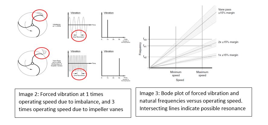
Up front dynamic analysis is sometimes warranted when using variable speed pumping to limit the risk of resonant vibration. Generally, HVAC pumps do not require upfront dynamic analysis, and rarely have it specified up front. The reasons dynamic analysis are seldom not done for HVAC pumps are:
- Most HVAC systems consist of primarily between-bearings or overhung horizontal pumps of a well-proven design, typically running at four-pole or slower speeds.
- Booster service typically uses vertically suspended pumps and smaller units often run at two-pole speed. These pumps are usually catalog units of well-proven design.
- The HVAC market is generally price-sensitive and competitive prices typically do not bear the cost of dynamic analysis.
However, vertically suspended pumps on variable frequency drives occasionally require a level 1 structural analysis to determine the reed frequency.
For more information about the HVAC and building markets and variable speed pumping, refer to ANSI/HI 9.6.8 Rotodynamic Pumps Guideline for Dynamics of Pumping Machinery and the “Pump Application Guideline for Commercial Building Services”.
February 2020
- What are some coatings used to resist wear and corrosion?
- Can coatings be applied to increase the efficiency of a pump?
-
How do you calculate the leakage rate of a mechanical seal?
Mechanical seals are precision devices that are designed to seal a rotating shaft; however, they do rely on a very small amount of leakage to lubricate and cool the seal faces. Leakage provides the lubricating film, which is imperative to ensure long life on the basis of normal wear of the sliding faces. A liquid-lubricated seal may have no visible leakage, indicating that the heating and pressure loss in the sealing gap has partly evaporated the fluid film and thus the leakage will be in gaseous form or not apparently visible.
The leakage rate of a mechanical seal depends on a wide range of factors:
- The roughness and general state of the sliding surfaces during assembly, and over the course of the service life
- Flatness of the sliding surfaces and any changes in flatness caused by heat, pressure, or mechanically related deformations
- The vibration level and mechanical stability of the pump
- Mode of pump operation, i.e., continuous or frequent start–stop
- The fluid characteristics
Image 1 shows three simplified and idealized pressure profiles in the sealing gap (h), for when the pump shaft is static (3), as the shaft starts to rotate (4), and finally the hydrodynamic zone (5) when the shaft is rotating, and the hydrodynamic pressure rises in the gap. In the hydrodynamic zone, when the opening forces equal the closing forces, the sealing surfaces run a film of liquid, normally without contact and thus resulting in negligible wear to the seal faces.
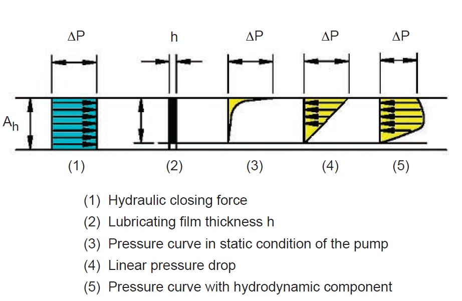
Image 1 – Pressure profile in the sealing gap (h)
The theoretical leakage rate of a liquid-lubricated mechanical seal can be calculated by the following equation:
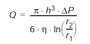
Where:
Q = leakage rate in m3/sec (in3/sec)
r1 = inner face radius in mm (in)
r2 = outer face radius in mm (in)
h = gap height in μm (μin)
ΔP = pressure differential in Pa (psi)
η = dynamic viscosity of the sealed fluid in Pa·s (lbf-sec/in2)
For example, if variables above are as we take the follows, the theoretical leakage rate (Q) is 0.34 milliliters per hours (5.86 x 10⁻⁶ cubic inches per second).
Example variables:
r1 = 26.98 mm (1.062 in)
r2 = 31.75 mm (1.25 in)
h = 0.254 μm (total surface roughness) (10 μin)
ΔP = 1.8 MPa (265 psi)
η = 1.0 X 10⁻³ Pa·s (1.45 x 10⁻⁷ lbf-sec/in2)
April 2020
- How should temperature measurements be used for monitoring the condition of rotary pumps?
-
When are combustion engine drivers used for pump applications?
The benefits of internal combustion engines are that they are capable of operating when electricity is not available such as remote applications, portable applications, or in the event of an emergency such as a fire when electricity for a motor may not be available. An additional benefit is that they are inherently capable of varying speed of the pump to meet the demands of the system. Image 1 is an example of an engine used for a fire pump (pumps used for fire suppression).
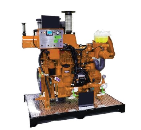
Image 1: Fire pump engine
However, in comparison to electric motors, there are other considerations when using combustion engine drivers. These drivers will be less efficient, require more regular maintenance and require additional cooling. The noise level will be higher, fuel will need to available and stored, and they exhibit increased risk of torsional vibration issues, especially on vertical pumps. A torsional analysis is sometimes performed. Consider checking with engine manufacturer for recommendations regarding analysis.
For more information about temperature sensors, temperature monitoring and fire pumps, refer to ANSI/HI 9.6.9 Rotary Pumps Guideline for condition monitoring, and search “pump system optimization”.
June 2020
- When testing rotodynamic pump efficiency, what is the standard method for testing?
-
Is there a simple way to check the alignment of flexible couplings on a pump?
Laser alignment systems are used to determine the extent of shaft misalignment by measuring the movement of a laser beam across the surface of a detector plate as the shafts are rotated. Many laser alignment systems are available, and the procedure for alignment is provided by the laser system’s producer. They are capable of aligning couplings with and without spacers and are most commonly used for precision alignments. Image 1 shows an example of a laser alignment system setup on a pump and motor shaft. By following the instructions of the laser system, the computer will output adjustment requirements to align the shafts.
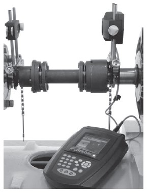
Image 1. Laser alignment system (Images courtesy of Hydraulic Institute)
In the absence of a laser alignment system, users can check the alignment with some simple tools. The necessary tools used for checking the alignment of a flexible coupling are a straightedge and a taper gauge or a set of feeler gauges, or by use of dial indicators.
A rough check for angular alignment is made by inserting the taper gauge or feelers between the coupling faces at 90 degree intervals (see Image 2). Checks for angular and parallel alignment by this method can only be done if the face and outside diameters of the coupling halves are square and concentric with the coupling bores. A rough check for parallel alignment is made by placing a straightedge across both coupling rims at the top, bottom and at both sides (see Image 3). After rough alignment, fasten the indicator to the pump half of the coupling, with the indicator button resting on the other half coupling periphery (see Image 4). Set the dial to zero, and mark the coupling half beside where the button rests. Rotate both shafts by the same amount, i.e., all readings on the dial must be made with button beside the mark. The dial readings will indicate whether the driver has to be raised, lowered or moved to either side.
After each adjustment, recheck both parallel and angular alignments. Accurate alignment of shaft centers can be obtained with the dial indicator method—even where faces or outside diameters of the coupling halves are not square or concentric with the bores—provided all measurements for angular alignment are made between the same two points on the outside diameters. For angular alignment, change the indicator so it bears against the face of the same coupling half and proceed as described for parallel alignment.
There are many additional techniques not described in this answer that are required for proper pump alignment, such as correcting for indicator sag or compensating for cold aligning a hot pump system. Please reference industry standards and the pump and coupling manufacturer’s instructions as well.
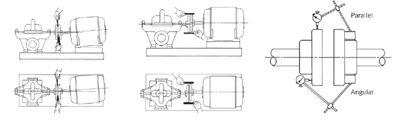
Image 2. Angular misalignment
Image 3. Parallel misalignment.
Image 4. Dial indicator
For more information about coupling alignment for rotodynamic pumps, including additional considerations, see the new American National Standard ANSI/HI 14.4 Rotodynamic Pumps for Manuals Describing Installation, Operation, and Maintenance.
April 2019
- What pump selection considerations are needed to handle wastewater?
-
What are the recommended valves in a pumping system?
A pumping system typically requires three valves: an inlet (suction) shut-off valve, an outlet (discharge) shut-off valve to provide system isolation, and a check valve located between the pump discharge nozzle and the discharge shut-off valve to avoid reverse flow and protect the pump from backpressure. Occasionally, a foot valve can be installed on the inlet pipe to maintain pump prime or to protect the pump from reverse rotation. However, potential drawbacks to foot valves such as impacts to net positive suction head available (NPSHa) and risk of water hammer (a pressure surge caused by an abrupt change in the pump rate of flow) must be considered.
Note that some systems will not require these valves, and some will require additional valves for isolation and control. Specification and application for these valves and control valves can be referenced in ANSI/HI 9.6.6 Rotodynamic Pumps for Pump Piping, and HI’s “Pump System Optimization: A Guide for Improved Energy Efficiency, Reliability, and Profitability.”
Sometimes, the discharge isolation valve and the check valve can be replaced by a triple-duty valve, which provides both isolation and back flow prevention in a single piece of equipment. These valves can also provide circuit balance. The initial installment of triple-duty valves is typically less expensive than the initial installment of separate valves; however, triple-duty valves may exhibit higher head loss, which could lead to higher life cycle costs in the long run. Refer to HI’s “Pump Life Cycle Costs: A Guide to LCC Analysis for Pumping Systems” for information on how to calculate the life cycle cost of a pumping system.
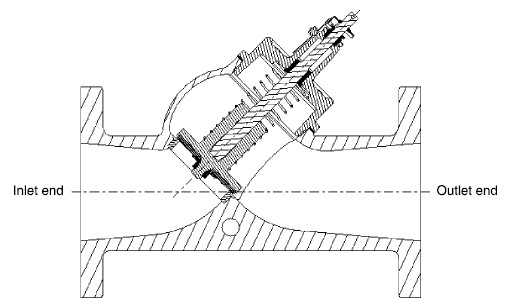
Image 1: Layout of a triple-duty valve (Images courtesy of the Hydraulic Institute)
September 2019
-
When selecting mechanical seals used in food and beverage applications, why materials consideration should be made?
A mechanical seal provides dynamic sealing and static sealing of the pumped fluid. Image 4 shows a simple mechanical seal illustrating the product side and atmospheric side of the seal. The product is sealed to atmosphere by static seals along the pump shaft and in the housing, and the mating surfaces of the rotating and stationary faces seal dynamically.
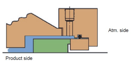
Image 4 Mechanical seal
Materials selection is important for mechanical seals and wetted components of a pump, due to factors like corrosion, product contamination, and chemical resistance.
This is of particular importance for pumps used in food and beverage applications, because it prevents toxic particles from entering the pumped fluid. Nickel is particularly suitable where resistance to caustic and other alkalis is required, and it is also useful for protecting product purity in the handling of foods and synthetic fibers. Nitrile, fluorocarbon, ethylene propylene, and PTFE materials are available in compounds suitable for use in food and beverage services. On the other hand, some grades of bronze are not acceptable for food service because of tin and lead content.
For more information on mechanical seals and their materials of construction, “Mechanical Seals for Pumps: A Cost-Saving Guide to Proper Selection, Installation & Operation”.
January 2020