![]()
Trimming Impellers to Reduce Energy Consumption
System design engineers typically “round up” system capacity and losses to leave room for everything from changes during construction and potential facility expansions to fluid viscosity changes and the gradual roughening of pipe surfaces over time. As a result, pumps in the field often run at higher pressures and flowrates than their application requires.
Category: Blogs, Energy Efficiency, Technical, PSM Newsletter September 27, 2022
Instead of throttling back powerful pumps, trim their impellers and slash energy costs.
System design engineers typically “round up” system capacity and losses to leave room for everything from changes during construction and potential facility expansions to fluid viscosity changes and the gradual roughening of pipe surfaces over time. As a result, pumps in the field often run at higher pressures and flowrates than their application requires. This not only wastes energy and money—a surprising amount of it—but it can also lead to unexpected cavitation issues and premature wear.
There are several common fixes for over-sized centrifugal pumps. Engineers can either throttle the pump using system valves or open a discharge bypass line to reduce overall flow to the system. Using valves to throttle the flowrate introduces an additional pressure loss in the system, which changes the shape of the system curve.
Opening a discharge bypass line recirculates a portion of the flow back to the suction source upstream of the pump. Although this option allows the system to operate at a reduced flowrate on the original system curve, the pump is consuming more energy than required and is therefore not energy efficient.
Another solution is to switch to a variable speed drive (or variable frequency drive), though this can be expensive or redundant if the application does not have multiple operating conditions that justify the expense.
There is a third option that is more efficient than throttling and costs far less than a variable speed drive: impeller trimming. It involves machining the impeller to reduce its outside diameter and shorten its vane length. This reduces the impeller’s peripheral velocity, which lowers the energy imparted to the pumped fluid. As a result, the pump’s flow rate, pressure, and required input power all decrease.
There is, of course, a tradeoff: trimming the impeller typically makes the pump less efficient. Trimming the outside diameter of the impeller increases the clearance between the impeller and the pump casing (or cutwater), generating more internal flow recirculation and decreasing the hydraulic efficiency (appearing as a loss in head). Yet even with this potential reduction in pump efficiency, the reduced head and flow rate result in lower system losses and less power consumption than using a throttle or bypass.
Understanding trim
Trim is an essential element when configuring centrifugal pumps. To achieve greater standardization, manufacturers design casings to accommodate several different impellers and trim ranges. In turn, engineers typically select the most efficient pump where the intersection of the pump curve and system curve occur near the maximum impeller diameter. That way, they can trim the diameter to reduce head or flow or they can retrofit the pump with a slightly larger impeller if they need to boost performance.
Because trim is an integral part of selecting a pump, most manufacturers provide pump performance curves that describe how their pumps will perform with different impeller trims. This provides a set of ready-made guidelines for engineers considering whether to trim a pump or not.
Still, there are several caveats users should keep in mind. First, they should not trim the impeller any smaller than the minimum diameter found on the manufacturer’s performance curve.
Second, they should also pay attention to net positive suction head required (NPSHR), the amount of inlet suction pressure needed to run the pump reliably without significant cavitation. It can vary with trimming. Most often, it decreases at lower flow rates, though it can rise exponentially as you approach shut-off. Engineers should consult with pump manufacturers to determine how trimming will affect NPSHR, since their supplier may have trim correction charts based on historical test data.
Trimming works best on radial impeller type centrifugal pumps. Mixed-flow impeller types can stand less reduction in diameter due to vane overlap and are traditionally trimmed more at the outlet/outside diameter and not at all near the hub. Axial-flow types are rarely trimmed and rely on vane (or blade) angle for flow and head reduction. If axial-flow types are trimmed, they require a liner to maintain running clearances with the housing inner wall. For multistage centrifugal pumps, removing stages is often a better option than trimming when large corrections are needed.
So, if impeller trimming makes sense in your application, contact the manufacturer for data. But what if that company has gone out of business or does not have performance curves you need? Then you can do the calculations yourself.
Trim calculations
A procedure closely associated with the affinity rules can predict how changes in impeller diameter affect pump performance. In fact, the Hydraulic Institute allows a 5% reduction in impeller diameter by using affinity rules to calculate the resulting performance. Never trim an impeller outside the manufactures recommendations or published performance curve or by default more than 75 percent of its maximum impeller diameter, since this can create instabilities and performance issues.
The affinity rules predict how changes in impeller diameter (or speed) will alter a centrifugal pump’s performance. The rules describe the relationship between flowrate, head, and pump input power based on speed and impeller diameter:
Q2/Q1 = D2/D1
H2/H1 = (D2/D1)2
P2/P1 = (H2Q2)/(H1Q1)
= (D2/D1) 3
where:
Q = pump flow rate (in gallons per minute)
H = head (in feet)
P = pump input power (in horsepower, hp, also referred to as brake horsepower, bhp)
D = impeller diameter (in inches)
1 following any variable will indicate performance or mechanical characteristics for the original or commissioned impeller.
2 following any variable will indicate performance or mechanical characteristics for trimmed impeller.
These equations show how any given point will change on the pump curve. While this is a simple linear ratio for flow rate, it is squared for head and cubed for power. In practice, system flow is not affected since impeller trimming typically eliminates throttling and its associated pressure loss.
The payoff
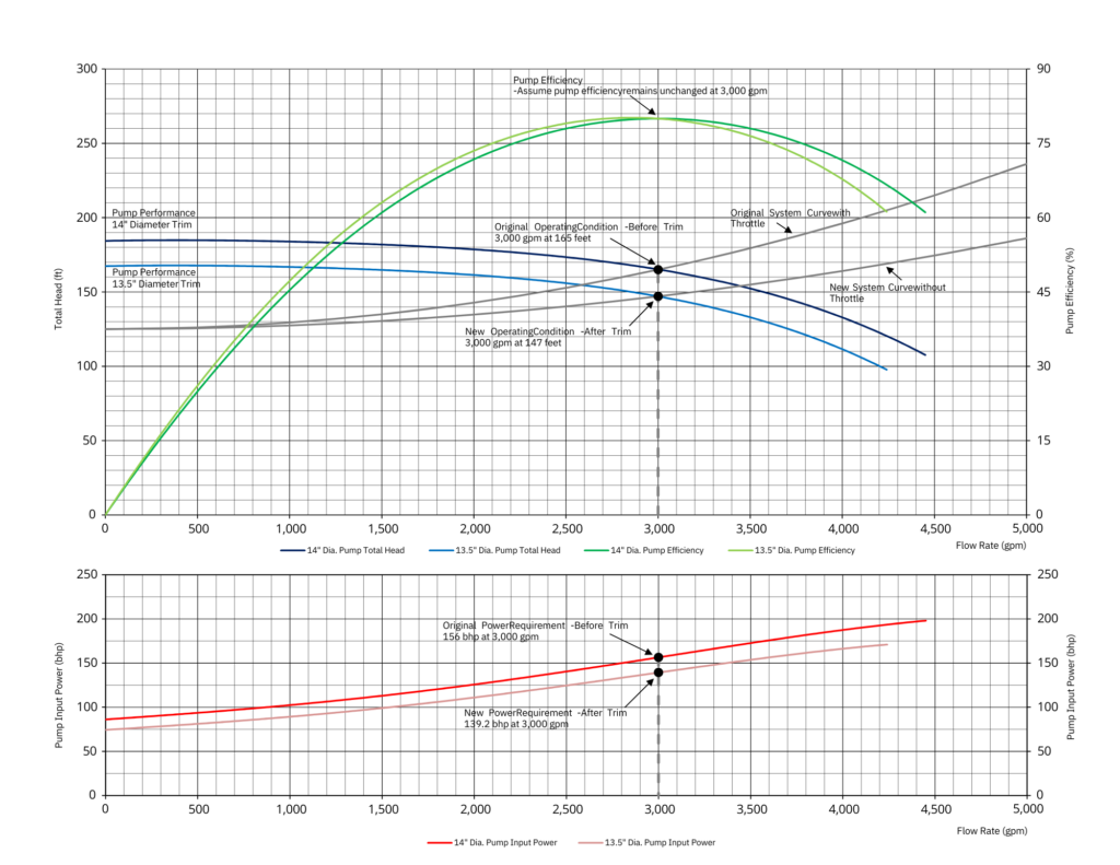
To understand how this plays out, let’s look at a double-suction centrifugal pump equipped with a 14-inch-diameter impeller that is throttled to provide a process cooling water flow rate of 3,000 gpm. The pumping system operates for 8,000 hours per year with a head of 165 feet and pump efficiency (η) of 80 percent. The pump required is156 hp.
Without adding the additional pressure loss by throttling the system curve indicates that a trimmed impeller can supply the required 3,000 gpm flowrate at a head of 147 feet. This would reduce the pump’s total head by 5.8 percent and increase the systems energy efficiency by lowering its energy consumption.
From the affinity rules, we can work out the diameter of the trimmed impeller as follows:
(H2Q2)/(H1Q1) = (D2/D1) 3
Holding Q constant,
D2 = D1 x (H2 / H1)1/3
= 14 x (147/165) 1/3
= 13.47 inches (rounded to 13.5 inches for trimming purposes)
Assuming that the pump efficiency remains unchanged, installing a 13.5-inch trimmed impeller reduces input power requirement to the following:
P2 = (H2Q2)/(3,960 x η)
= (147 x 3,000)/(3,960 x 0.8)
= 139.2 hp
This has a significant impact on estimated energy savings. Assuming a 94 percent efficient motor (η=0.94), the cost savings come to:
(P1-P2) x 0.746 kW/hp x 8,000 hours/year /0.94 = 106,662 kWh/year
At an electricity cost of 12 cents/kWh, total estimated cost savings are $12,800 per year.
Those are significant savings and may justify trimming the impellers of oversized pumps. To dive into the details, refer to Hydraulic Institute standard ANSI/HI 14.3-2019 Rotodynamic Pumps for Design and Application.
SUBSCRIBE TODAY
Get the latest pump industry news, insights, and analysis delivered to your inbox.