
Water Distribution Pump—Eliminate Bypass Pressure Control
A water supply system pumped water from a river using a 112 kW (150 hp) pump, as well as two backup pumps for high flow demands. A pressure control valve was originally used to maintain constant pressure but resulted in wasted flow. The pressure control valve was replaced with a pressure control system and a VFD which resulted in lower cost of operation.
Category: Blogs, Case Studies September 9, 2026
Intended Audience: Water Distribution
Objective: Eliminate waste from flow diversion pressure control to reduce cost of operation.
Description of System: As shown in Figure 1, a water supply system pumped water from a river to a large research complex. A main 112 kW (150 hp) pump was supplemented by a 37-kW (50 hp) and 186 kW (250 hp) pump to meet high flow demands and when the 112 kW (150-hp) pump tripped on overload. The total flow from the 112 kW (150 hp) pump was a constant 386 m3/h (1700 gpm) at a pressure set point (SP) of 896 kPa (130 psi). The pressure was maintained by an open diverter valve that averaged 159 m3/h (700 gpm) flow back to the supply tank.
A 149 kW (200 hp) motor was proposed to be installed in place of the 112 kW (150 hp) motor. This would eliminate the overload tripping events but would not eliminate the wasteful operation of the flow diversion pressure control. Before the motor was purchased, a pumping system assessment was completed.
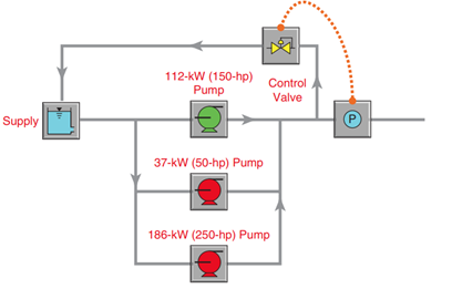
Figure 1: Initial Installation and Control Diagram
As shown in Figure 2, on average, the main pump drew 116 kW (156 hp), and the other pumps would be started on occasion when the main pump tripped or when the flows exceeded its capacity at the 896 kPa (130 psi) SP. The electricity cost to operate this system was $40,000 per year. This did not include wear and extra maintenance required on the pressure control valve.
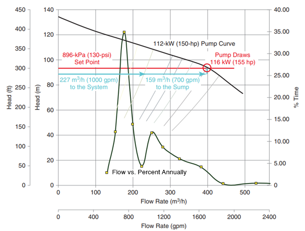
Figure 2 : Operating Condition Before Modification
Description of Intervention: As shown in Figure 3, following the pumping system assessment, the pressure SP was reduced to 690 kPa (100 psi), the 112 kW (150 hp) motor was rewound for inverter duty, a VFD was installed, and a pressure control system was programmed to vary the speed of the pump and eliminate the flow diverter valve loop so that all of the flow from the pumps was going into the system. The net customer cost of the upgrades was $39,000 after a utility subsidy paid for 40% of the $65,000 total project cost
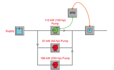
Figure 3: Modified Installation and Control Diagram
As shown in Figures 4 and 5, the savings were from reducing the high-pressure SP and eliminating the wasted flow through the diverter valve piping. The high pressure was only required on rare occasions at the facility, and the VFD pump could be ramped up to meet that demand. The diverter valve piping required replacement before the pump assessment was conducted due to wear from cavitation downstream of the valve. The cost history of maintaining the valve was annualized to $1,333 per year and included the non-energy savings for the project.
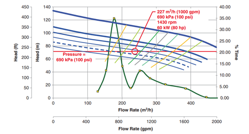
Figure 4: Average Operating Conditions
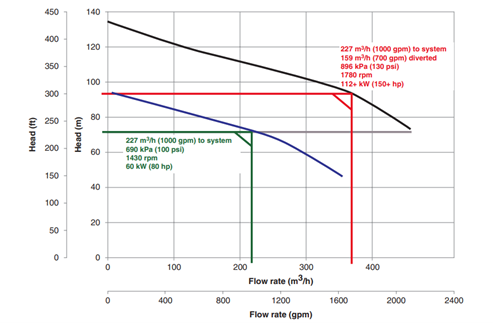
Figure 5: Comparison of Operating Points
Summary of Results: Table 1 shows the return on investment for upgrading the system.
Table 1: Return on Investment (ROI) Calculation
| Electricity Cost Before Installation | $40,000 |
| Electricity Cost After Installation | $22,00 |
| Electricity Cost Annual Savings | $18,000 |
| Avoided Annualized Valve Maintenance | $1333 |
| Total Annual Savings | $19,333 |
| Project Cost | $65,000 |
| Utility Funding | $26,000 |
| Net Project Cost | $39,000 |
| Simple Payback | 2.0 Years |
| Project Life | 15 Years |
| IRR | 49% |
Conclusion: Replacing a diverter valve with a VFD pump can often result in a more efficient system.
Written by:
Members of the Application Guideline for Variable Speed Pumping Committee, 1st Edition
Published In: Application Guideline for Variable Speed Pumping Committee, 1st Edition
Year of Publication: 2017
SUBSCRIBE TODAY
Get the latest pump industry news, insights, and analysis delivered to your inbox.