![]()
Pump Pros Know- Variable Frequency Drives
What do Pump Pros Know and why do they know it? This series of articles highlight the brilliance of those who work with pumps.
Understanding Variable Frequency Drives and their Interactions with AC Motors
A variable frequency drive (VFD) is a specific type of adjustable speed drive used for regulating the rotational speed of an electric motor. This is done by modulating the frequency of the electrical power supplied to the motor. Also called adjustable frequency drives (AFD), variable speed drives (VSD), AC drives, and inverters, VFDs are best applied in friction head-dominated pumping systems that undergo frequent load swings.
This article covers VFD control of conventional three-phase induction motors using the most common form of control, known as pulse width modulation (PWM). For additional information, please consult Application Guideline for Variable Speed Pumping, and Variable Frequency Drives Guidelines for Application, Installation and Troubleshooting, two guidebooks published by the Hydraulic Institute. Of course, local, and national codes and regulations must always be followed when installing VFDs and other electrical equipment.
VFDs in pump systems are now a mature technology that can yield large benefits by reducing operating costs and improving reliability in certain applications. VFDS can help pump systems accommodate the following:
- Varying operating conditions, such as changes in flow and system head for process control.
- Reduce the number of components within the pumping system.
- Reduce energy consumption and life cycle costs of both mechanical and electrical systems.
- Drive three-phase motors from single-phase power.
- Reduce inrush current and mechanical stresses at start-up.
- Limit hydraulic system pressure transients.
Operating Principles
A VFD is a commonly used method for regulating the speed of an AC motor. The system typically includes a VFD control, which can employ various methods to adjust the motor speed. Some examples of these methods include a simple dial potentiometer, pushbutton, or keypad, while others involve more complex automatic control systems that use feedback from sensors such as flow, level, and pressure to regulate the frequency output to the motor. While details about these sensors are beyond the scope of this article, additional resources can be consulted for more information.
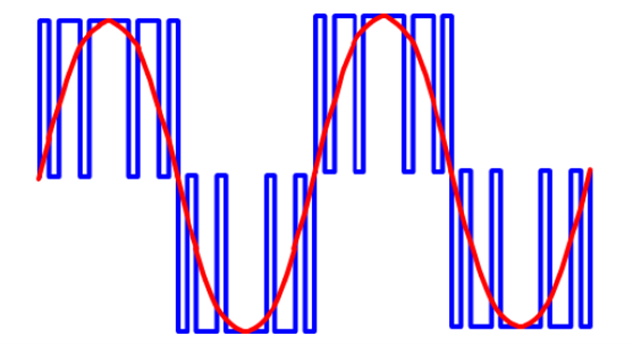
VFD controllers use solid-state electronic power components to convert AC input power into intermediate DC power, which is then converted into simulated AC output power using an inverter. PWM is the most common technology used for adjusting the motor frequency and voltage in an inverter. A PWM inverter achieves this by varying the width and polarity of the output voltage pulses and using a carrier frequency that is much higher than the frequency of the simulated sinusoidal output. By switching the power on and off so rapidly, the resulting power waveform closely approximates the sinusoidal power that is normally supplied to a motor, enabling the VFD controller to modulate the speed and torque delivered by the AC electric motor (Figure 1).
Figure 1: VFD output PWM (blue) waveform with corresponding sine wave (red)
Due to the conversion of incoming power to DC, certain VFDs can receive single-phase input power and deliver three-phase output power for driving three-phase motors. This can be beneficial in situations where three-phase power may not be available, or economically justified. These VFDs function as both phase converters and speed controllers. However, if the VFD powers a three-phase device, it must be de-rated when using a single-phase input.
Motor Considerations
AC motors operate based on the principle that the synchronous speed is determined by the frequency of the power supply and the number of poles in the motor’s stator winding. Table 1 illustrates how the synchronous speed is a function of the motor poles and the incoming line frequency (50 Hz or 60 Hz).
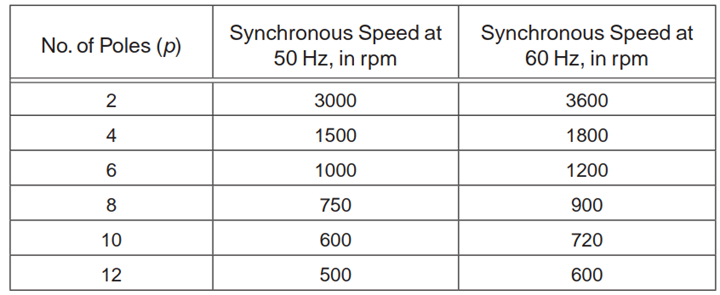
Table 1 – Synchronous speed for 2-pole to 12-pole motors at 50 Hz and 60 Hz.
Induction motors run at a speed slightly less than synchronous. For example, a four-pole motor (1,800 rpm synchronous) typically operates around 1780 rpm at full-load. The difference between the synchronous speed and actual speed is known as slip. Slip is inherent to induction motors and must be present for them to develop torque. The amount of slip (typically 1-3%) varies by motor power rating and design.
The full-load speed of a motor is typically indicated on its nameplate. It’s important to note that when a motor is operating from a VFD, the motor performance will be affected slightly compared to typical line power. In addition to temperature rise and incremental efficiency, the slip may also be affected. Therefore, it is recommended to refer to motor data sheets that include performance data for VFD operation and consult with the manufacturer if there is a concern.
Starting and Stopping
When a VFD starts a motor, it initially applies a low frequency (2 Hz or less) which results in low voltage to the motor. The VFD then ramps up the desired output frequency in a controlled and gradual manner, compared to across-the-line starting. The applied motor voltage ramps based on the V/Hz (volts to hertz) ratio characteristics set in the VFD. The V/Hz characteristics should match the torque load requirements. Too high a voltage at any given frequency wastes energy and can cause overheating; too low a ratio may generate insufficient torque.
Starting at a low frequency and voltage and ramping to the set V/Hz controls the accelerations and prevents the high inrush current that otherwise occurs when starting a motor with across-the-line power by turning on a switch or contactor. This starting method allows a motor to develop rated torque without drawing in-rush current of 500 to 600% of rated current. In general, the VFD peak current demand when starting a motor is 150% of full load current.
The torque available to start the load is important to consider. Figures 2 and 3 show the rotodynamic pumps have reduced torque at reduced speed, while positive displacement pumps can have full torque at reduced speed. This makes rotodynamic pumps easier to start with a VFD than positive displacement pumps. This speed torque profile must be considered when selecting and setting up the VFD. Additionally, system start up procedures my need to be followed when starting positive displacement pumps, such as bypassing flow (reducing pressure) until the motor has ramped up to speed.
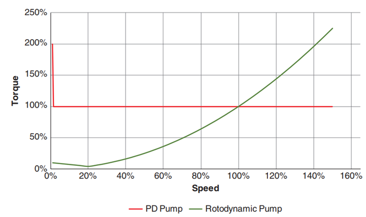
Figure 2 – Speed Torque requirements for Positive Displacement and Rotodynamic Pumps.
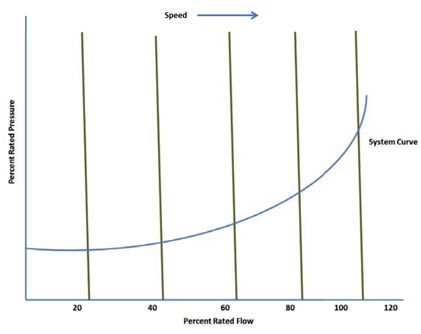
Figure 3 – Positive Displacement (green curves) can reach full pressure at reduced speed.
The stopping sequence for a VFD is the opposite of the starting sequence. The V/Hz applied to the motor are ramped down at a controlled rate. As the frequency approaches zero, the VFD output is electronically switched off, and the motor is no longer driven by the VFD. If the ramps are set too fast, the motor can produce regenerative energy which can increase the DC buss voltage and potentially damage the drive.
In addition to the lower in-rush current, the controlled acceleration, when starting and stopping the motor, reduced mechanical stresses and limits hydraulic system transients. The reduced mechanical stresses can lengthen the life of torque and load carrying components. The reduction of hydraulic transients levels out pressure spikes which otherwise could rupture the piping.
Other Considerations
When looking for a motor to use with a VFD, there are several factors to consider. However, the primary consideration is whether the motor and pumping application are suitable for VFD use. To make this determination, several factors must be taken into account.
Motor winding insulation — VFD power circuits utilize semiconductor switching technology, which can result in high-frequency spikes being imposed onto the motor winding through typical voltage and current output of a VFD. It is essential to determine the motor winding insulation’s capacity to withstand these spikes.
Motor bearings — VFDs can cause common mode voltages (CMVs) when driving three-phase motors. CMV is a voltage potential between at least one phase and voltage source ground and can cause a buildup of shaft voltage that needs to discharge. This can occur through the motor bearing if protective features are not added and can cause serious damage to the bearings and motor. A combination of a shaft grounding system and electrical isolation of the shaft, motor bearing, and proper grounding should be used.
Pump-motor operating speed range — The primary purpose of using a VFD in a pumping application is to optimize system efficiency and/or process control by varying the pump’s speed. By adjusting the voltage and frequency applied to the motor, the speed is typically lowered. It is possible to adjust the speed over the design speed. However, it is crucial to consult the pump/motor original equipment manufacturer (OEM) for operation above rated speed.
Lowering the motor speed usually results in a reduction in the motor cooling system’s capacity, which is typically not an issue for rotodynamic pumps due to their variable torque characteristics (Figure 2) but becomes a greater consideration for positive displacement pumps because they can operate at full pressure (constant torque) while at reduced speed (Figure 3). Since higher torque is required at reduced speed for positive displacement pumps it also makes them more difficult to start. Thus, it is vital to define and apply the operating speed range to meet the motor capability requirements.
Rotor and Structural Resonance — Operating a pump and motor combination at various speeds increases the potentially to excite natural frequencies of the rotating system or structure. With the growth of VFD use, vibration related to resonance is much more common, and can be very costly to address after the fact. As a first pass consulting with the manufacturer regarding the excitation frequencies for the pump in question and if there are known resonance issues in the operating speed range. However, the manufacturer may not be able to provide direct answer to this question for certain designs and in these cases prior to adding variable speed operations, it is essential to consider if the excitation frequencies will be amplified and the consequences of resonance as outlined in ANSI/HI 9.6.8 Rotodynamic Pumps Guideline for Dynamics of Pumping Machinery.
Controlling the VFD
Once you have determined the application and load characteristics, you can select the appropriate motor. The motor data and application speed range will then dictate the selection of the VFD and control system. Programming can usually be configured, and parameters can be adjusted through an operator interface. This allows the user to customize the VFD controller to suit specific process, motor, and driven equipment requirements. Additional control functions might include jogging and switching between manual speed adjustment and automatic control from an external process control signal.
Most VFDs have a keypad and display that can be mounted remotely. Most also come equipped with input and output (I/O) terminals for connecting pushbuttons, switches, and other operator interface devices or control signals. Additionally, a serial communications port is often provided, allowing the VFD to be configured, adjusted, monitored, and controlled using a computer or other external controller.
Check out the other Pump Pros Know!