![]()
Eight Tips to Boost Pump Piping Efficiency
When it comes to optimizing pumping systems, the piping and additional end-use equipment are just as important as the pump itself. Here are eight ways you can assess your piping system’s configuration to minimize life-cycle costs.
Category: PSM Newsletter, Blogs February 2, 2023
When it comes to optimizing pumping systems, the piping and additional end-use equipment are just as important as the pump itself. Here are eight ways you can assess your piping system’s configuration to minimize life-cycle costs.
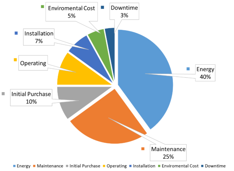
Select the proper pipe diameter. Cost plays a big role when specifying piping. While smaller diameter pipes cost less, the higher friction and overall head loss generated through the increased velocity is significantly greater. As a result, systems with smaller pipes may require more power or even a larger pump, and those energy costs will accrue over the lifetime of the system. Larger diameter pipes, on the other hand, have higher material and installation costs, but generally lower friction losses. To optimize a piping system, make sure to consider both initial costs and the extra energy required to use smaller diameters. There are several software packages that can help you calculate the life-cycle costs associated with the variety of pipe sizes required for complexed systems. The Hydraulic Institute offers a Pump System Optimization and Assessment course that covers the tools and software to support these calculations as part of pump system optimization.
Minimize pressure drops. Poor flow profiles will promote uneven flow and increase energy costs within a pumping system. Unfortunately, space constraints often preclude ideal piping system layouts. In this case, look for ways to smooth out sharp bends and expansion and contraction transitions. Also, keep your pipes as straight as possible. When designing new systems, install valves and system components so they are in line with the pipe run.
Choose low-loss components. Service requirements, such as maximum working pressure, open and close cycles, handwheel torque, and stem leakage, often drive valve selection. Often, for applications in which overall service requirements are modest, designers typically trade efficiency for upfront cost. Take globe valves, for example. Engineers like them because they are simple and inexpensive, but the flow path through the valve has a relatively high coefficient of friction. Switching to a different type of valve may decrease those losses and the overall life-cycle cost of the pumping system. For designers and assessment professionals who want to dive deeper, the Hydraulic Institute offers a free web-based Engineering Data Library (edl.pumps.org) that provides the resources to determine the typical resistant coefficients for valves and other fittings.
Size valves properly. System designers often add safety margins and oversize pumps to incorporate safety margins to account for such unknowns as actual pump performance, pipeline fouling and scaling, and future system demands. This safety margin often leads to engineers to specify a larger pressure drop across the valve than necessary. The result is an undersized valve that has a high energy or friction loss. The same is true when specifying valves to handle maximum system flow. Designing for much greater than normal flow creates excessive pressure drops across the valve under typical operating conditions.
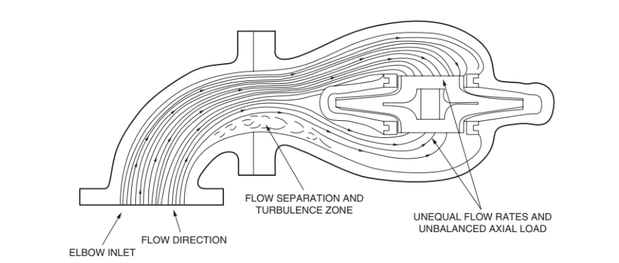
Provide uniform flow into the pump. Rotodynamic pumps operate most efficiently with a uniform inlet flow profile. This smooths the fluid’s transition from the suction nozzle to the impeller eye, which then imparts energy to the fluid by accelerating it along the vane to its tip. If the flow is nonuniform, it will prevent the smooth transfer of energy. Non-uniform flow may also cause excessive vibration, which can shorten pump life, and weaken pipe welds, mechanical joints, and supports. When designing new pumping systems, provide as much straight pipe as possible upstream of pump suction nozzles. For existing systems, the closer short-radius elbows and valves are to the suction nozzle, the more likely they will create highly turbulent flow that diminishes pump performance. This is particularly important when the suction pressure into the pump is low and the velocity is high. Figure 2 shows the flow separation and turbulence zone of a short-radius elbow mounted directly to the suction nozzle of a double suction pump. If an elbow is required just upstream of the suction nozzle, consider switching it to a long-radius elbow or install flow straighteners, such as baffle plates or turning vanes in the elbow to smooth the transition into the pump. This works well as long as the pressure drop across the straightener does not infringe on the necessary NPSH margin.
Limit air and vapor entrapment. Air or vapor entrapment is the result of a poor system layout or fitting selection. The collection of air or vapor occurs when the pumping system does not have a constant rising slope or it lacks air release valves at high points. When this occurs downstream of the pump, the air or vapor pockets reduce the effective liquid flow area within the pipe creating a throttling effect similar to a partially closed valve. For piping upstream of the pump, the pockets may cause pressure pulsations that degrade the performance of the pump. If space permits, use eccentric reducers and sufficient straight pipe leading up to the pump suction nozzle.
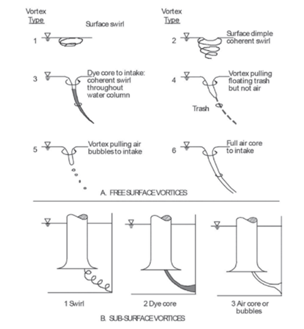
Suppress vortex formation. Free surface vortices occur in both tanks and wet wells when the fluid level drops too close to the suction inlet of a pump or submerged suction piping. When free surface vortices appear (see figure 3), air will enter the pump. This could trigger a loss of suction head and degrade performance. In severe cases, the pump could lose its prime. Since most centrifugal pumps are not self-priming or submersible, service personnel would have to fill, restart, and vent the pumps manually. Also, too much air could damage mechanical seals, packing, and impeller wear rings. Monitoring water levels with simple sensors or using an automated water level system will ensure the pump or suction piping has adequate submergence. For degraded pump performance, or mechanical issues dealing with submerged vortices, please reference ANSI/HI 9.8 Rotodynamic Pumps for Pump Intake Design.
Support your piping. A pump and its connected piping rarely align perfectly during installation. To accommodate this, installers or service personnel turn to manual mechanical corrections. If they are significant, this mechanical pipe strain force will pull the pump out of alignment, reduce service life, and, in severe cases, cause catastrophic failure. To prevent this from happening, piping around the pump should be properly supported and restrained using pipe anchors and hangers. This also reduces vibration and extends pump service life.
To learn more about this topic, visit (pumps.org/standards) and reference the Hydraulic Institute Standards ANSI/HI 9.6.6-2022 Rotodynamic Pumps for Pump Piping, ANSI/HI 9.8-2018 Rotodynamic Pumps for Pump Intake Design, ANSI/HI 14.3-2019 Rotodynamic Pumps for Design and Application, and ANSI/HI 9.6.2-2021 Rotodynamic Pumps for Assessment of Applied Nozzle Loads.
SUBSCRIBE TODAY
Get the latest pump industry news, insights, and analysis delivered to your inbox.